Resilient rotation buckle

a technology of rotating buckles and fixing iron plates, which is applied in the direction of fastening devices, wing accessories, manufacturing tools, etc., can solve the problems of affecting the operation of turning plates, etc., to achieve the effect of simplifying the machining process, eliminating noise, and facilitating the turn over operation

Active Publication Date: 2012-11-06
CHEN HSI HSIN
View PDF23 Cites 6 Cited by
  • Summary
  • Abstract
  • Description
  • Claims
  • Application Information

AI Technical Summary

Benefits of technology

[0004]In view of the above discussed problems, an objective of the present invention is to provide a resilient rotation buckle that allows for easy and smooth turn over of the buckle for switching between two surfaces thereof, that allows for easy manufacturing, and that allows for automatic turn-over positioning after the resilient rotation buckle has been rotated for a predetermined angle.
[0006]Compared to the conventional techniques, the present invention offers the following advantages. The present invention provides a resilient rotation buckle that comprises a rotation shaft that in the form of a prism having a cross-sectional shape comprising opposite arc flanks, so as to facilitate the turn over operation of the resilient rotation buckle, allow the resilient rotation buckle to automatically complete the turn over operation by only rotating the buckle to a predetermined angle, eliminate noise caused thereby, and simplify the machining process thereof.

Problems solved by technology

Generally speaking, both the belt buckle and a belt attached to the buckle are of fixed decorations or patterns and are not good for wearing in different occasions, making them poor in use.
Since in use, a user must apply a force to the turning plate in a very complicated manner, it is often that the fixing iron plates jam in the un-slotted portion of the central shaft.
This affects the smooth rotation of the turning plate, causes noises, and even blocks the rotation of the turning plate.
This increases the difficult of machining and also raises the costs.

Method used


Image

  • Resilient rotation buckle
  • Resilient rotation buckle
  • Resilient rotation buckle

Examples


first embodiment

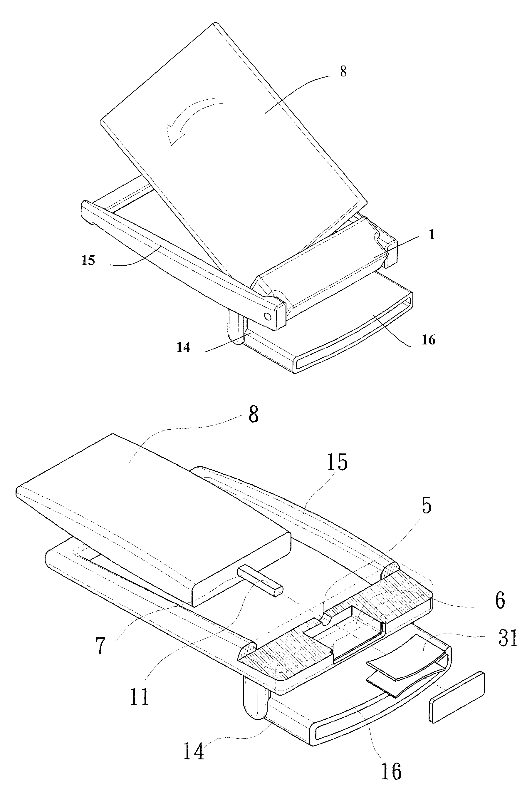
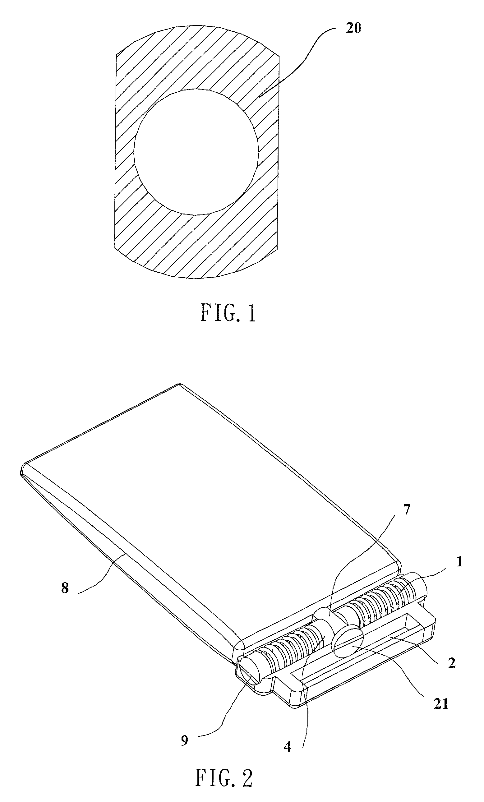
[0036]FIGS. 11 and 12 show the present invention, wherein the resilient rotation buckle of the present invention comprises a decoration plate 8, a belt coupling structure 14, a rotation shaft 7, and a rotation assembly 1. The belt coupling structure 14 comprises a hollow frame 15 and a belt clamping structure 16 that is formed on a lower side of the frame 15 for clamping and fixing a belt. The rotation assembly 1 is pivotally connected to the frame 15 at an end close to the belt by a pivot pin that is substantially parallel to an upper surface of the frame 15. In normal use, the decoration plate 8 has an end that is coupled to the rotation assembly 1 by the rotation shaft 7 attached thereto (as shown in FIG. 11) and an opposite end that is free and positioned on the frame 15. To turn the decoration plate 8 over the free end of the decoration plate 8 is lifted upward by rotation about the pivot pin by a predetermined angle so as to turn the rotation assembly 1 upwards to the predeter...

third embodiment

[0038]FIG. 14 shows the present invention, of which the resilient rotation buckle according to the present invention comprises a decoration plate 8, a belt coupling structure 14, a rotation shaft 7, and a rotation assembly 1. The belt coupling structure 14 comprises a support base 17 that functions to support the decoration plate 8 thereon and has a buckling end 18 to which the rotation assembly 1 is pivotally connected and an opposite end forming a belt clamping structure 16 for clamping a belt. The decoration plate 8 has an end forming the rotation shaft 7 and an opposite end forming a locking structure that is engageable with the belt clamping structure 16. The decoration plate 8 is rotatably coupled to the rotation assembly 1 through the rotation shaft 7. In normal use, the decoration plate 8 is set on the support base 17. When it is desired to turn the decoration plate 8 over, the free end of the decoration plate 8 is lifted upward by rotation about the pivotal connection to tu...

fourth embodiment

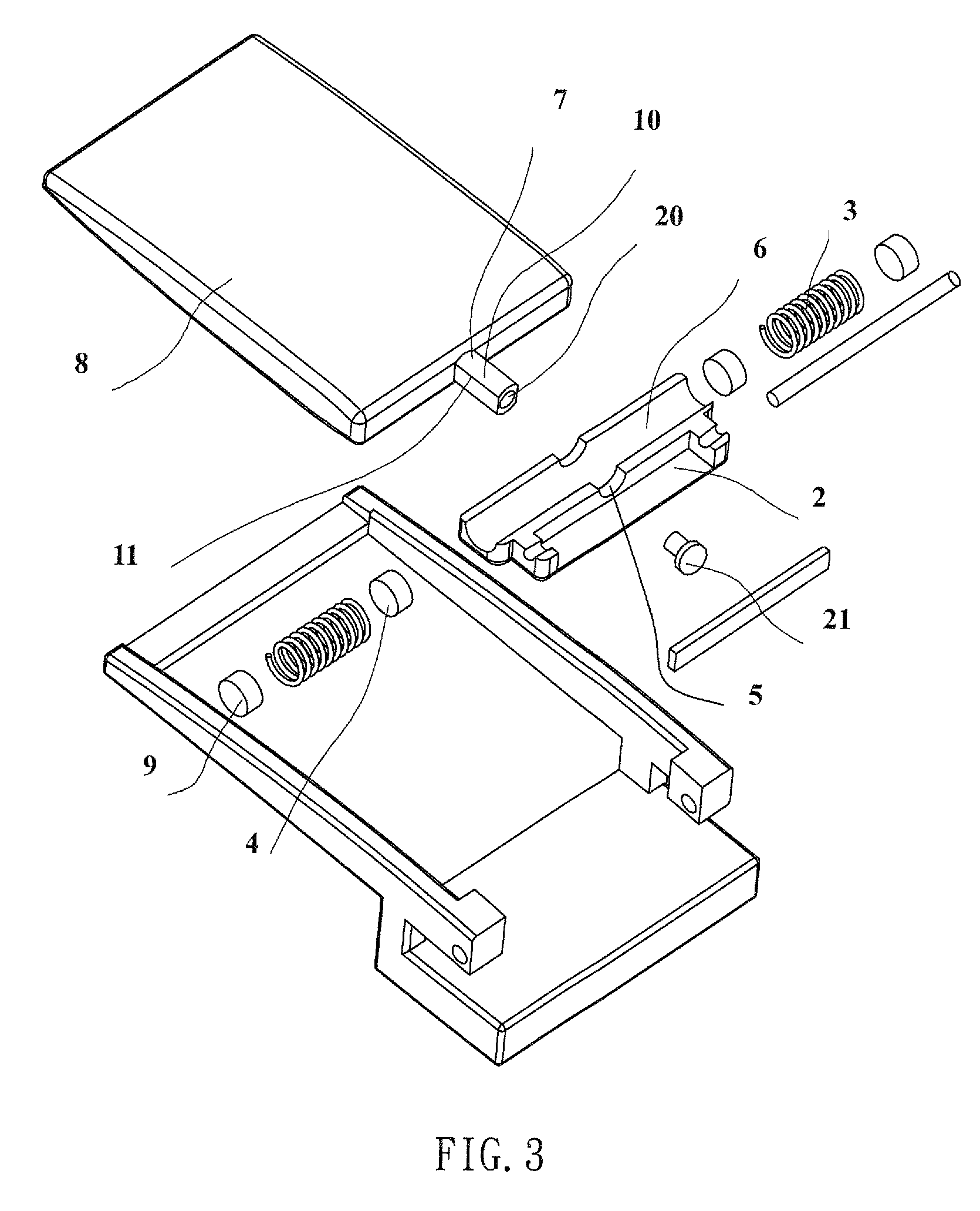
[0039]FIG. 15 shows the present invention, of which the resilient rotation buckle according to the present invention comprises a decoration plate 8, a belt coupling structure 14, a rotation shaft 7, and a rotation assembly 1. The belt coupling structure 14 comprises a hollow frame 15 having an end forming on a bottom thereof a belt clamping structure 16. The rotation assembly 1 is also mounted to the end of the frame 15. The decoration plate 8 has an end forming the rotation shaft 7 and the decoration plate 8 is rotatably coupled to the rotation assembly 1 through the rotation shaft 7 for being positioned in the frame 15. When it is desired to turn the decoration plate 8 over, the decoration plate 8 is rotated about the rotation shaft 7 in either the clockwise direction or the counterclockwise direction to an angle of approximately 130 degrees, where the decoration plate 8, under the action of the spring forces of the springs 3, automatically returns to the locked position shown in ...


PUM


Abstract

A resilient rotation buckle includes a decoration plate and the belt coupling structure having an end coupled to a belt. The decoration plate and the belt coupling structure form a rotation shaft and a rotation assembly that cooperate each other. The rotation assembly includes a receptacle compartment having a wall forming a through hole for receiving the rotation shaft therethrough, springs, and retention blocks. An accommodation channel is defined in the receptacle compartment in a direction normal to the through hole. When the rotation shaft is inserted, the retention blocks are in contact engagement with an outer circumference of the rotation shaft. The springs have first ends in biasing engagement with the retention blocks and second ends supported by walls of the accommodation channel. The rotation shaft and the rotation assembly allow for relative rotation therebetween for switching between a locked position and a released position.

Description

(a) TECHNICAL FIELD OF THE INVENTION[0001]The present invention generally relates to a belt fastening structure, and more particularly to a resilient rotation buckle.(b) DESCRIPTION OF THE PRIOR ART[0002]A belt buckle is often used to secure clothes and trousers and is also used for decoration purposes. Generally speaking, both the belt buckle and a belt attached to the buckle are of fixed decorations or patterns and are not good for wearing in different occasions, making them poor in use. A belt with a turn-over buckle is available in the market, having different patterns or decorations formed on opposite surfaces of the buckle or those of the belt. Thus, by turning the belt buckle over, different patterns can be switched. This meets the needs of people attending different occasions.[0003]Chinese Patent No. 200720047277.5 discloses a dual purpose buckle having a retention plate that is capable of turning over, comprising a fixing plate, a positioning retention plate, a dual-sided t...

Claims


Application Information

Patent Timeline
Patent Type & Authority Patents(United States)
IPC IPC(8): A44B11/00A44B11/22A41F9/00
CPCA44B11/001A44D2211/00Y10T16/53864Y10T16/5472Y10T24/4098Y10T24/4037
Inventor CHEN, HSI-HSIN
Owner CHEN HSI HSIN
Why Eureka
Try Eureka