Resilient rotation buckle
- Summary
- Abstract
- Description
- Claims
- Application Information
AI Technical Summary
Benefits of technology
Problems solved by technology
Method used
Image
Examples
first embodiment
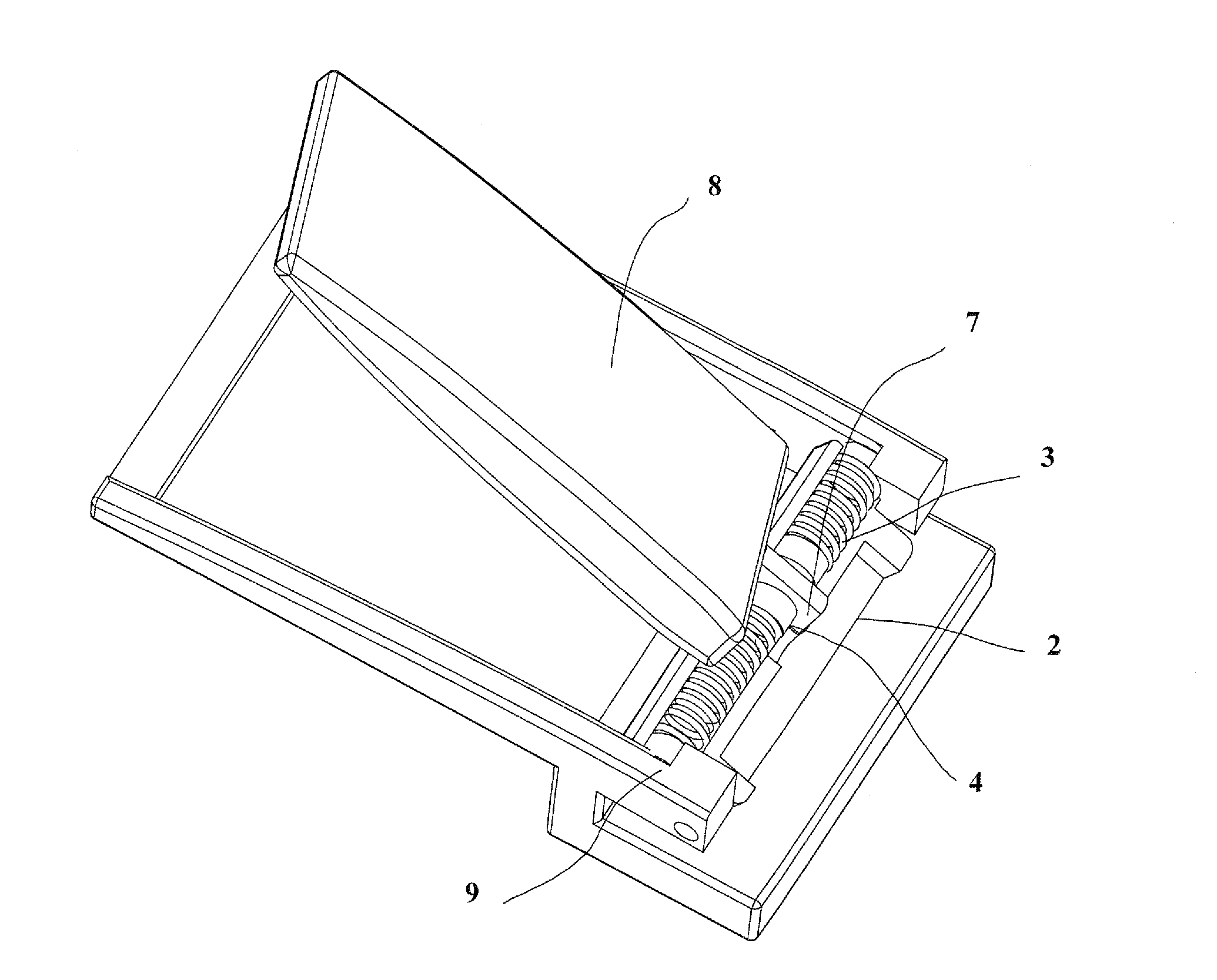
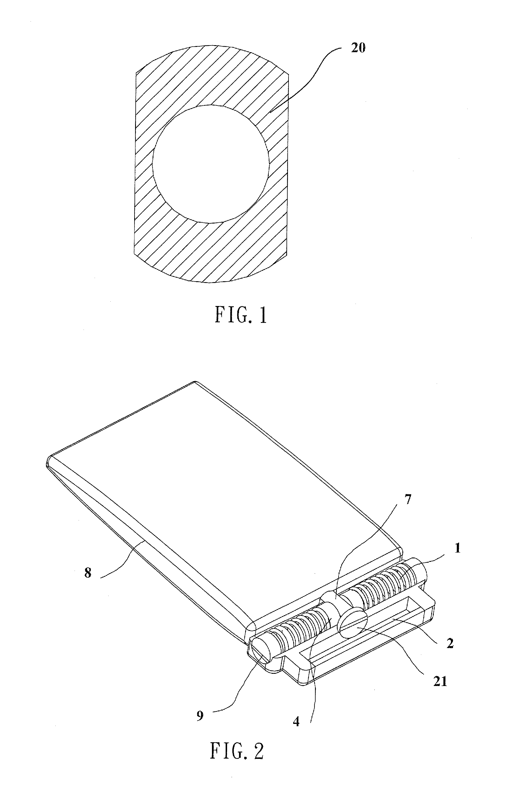
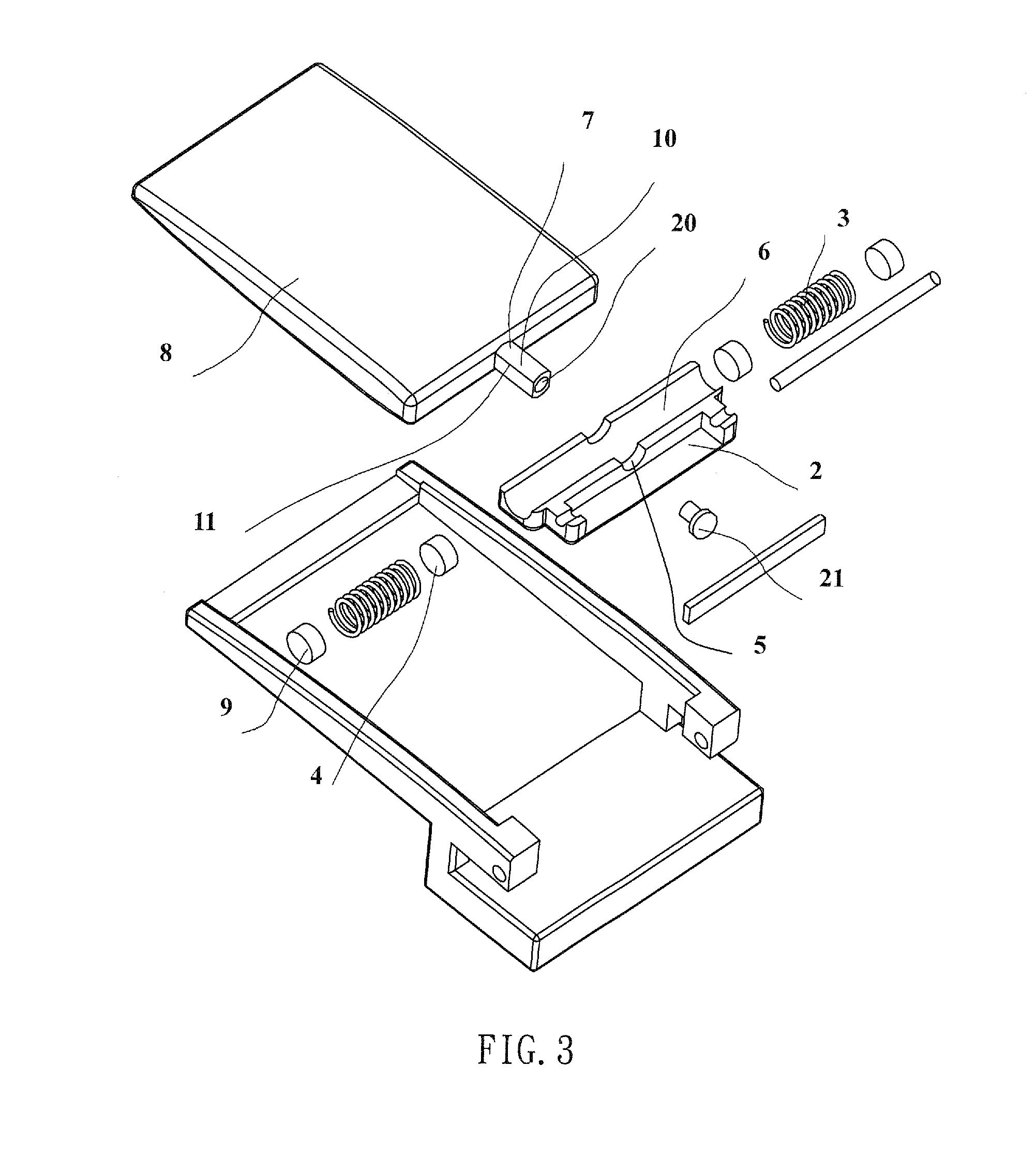
[0036]FIGS. 11 and 12 show the present invention, wherein the resilient rotation buckle of the present invention comprises a decoration plate 8, a belt coupling structure 14, a rotation shaft 7, and a rotation assembly 1. The belt coupling structure 14 comprises a hollow frame 15 and a belt clamping structure 16 that is formed on a lower side of the frame 15 for clamping and fixing a belt. The rotation assembly 1 is pivotally connected to the frame 15 at an end close to the belt by a pivot pin that is substantially parallel to an upper surface of the frame 15. In normal use, the decoration plate 8 has an end that is coupled to the rotation assembly 1 by the rotation shaft 7 attached thereto (as shown in FIG. 11) and an opposite end that is free and positioned on the frame 15. To turn the decoration plate 8 over the free end of the decoration plate 8 is lifted upward by rotation about the pivot pin by a predetermined angle so as to turn the rotation assembly 1 upwards to the predeter...
third embodiment
[0038]FIG. 14 shows the present invention, of which the resilient rotation buckle according to the present invention comprises a decoration plate 8, a belt coupling structure 14, a rotation shaft 7, and a rotation assembly 1. The belt coupling structure 14 comprises a support base 17 that functions to support the decoration plate 8 thereon and has a buckling end 18 to which the rotation assembly 1 is pivotally connected and an opposite end forming a belt clamping structure 16 for clamping a belt. The decoration plate 8 has an end forming the rotation shaft 7 and an opposite end forming a locking structure that is engageable with the belt clamping structure 16. The decoration plate 8 is rotatably coupled to the rotation assembly 1 through the rotation shaft 7. In normal use, the decoration plate 8 is set on the support base 17. When it is desired to turn the decoration plate 8 over, the free end of the decoration plate 8 is lifted upward by rotation about the pivotal connection to tu...
fourth embodiment
[0039]FIG. 15 shows the present invention, of which the resilient rotation buckle according to the present invention comprises a decoration plate 8, a belt coupling structure 14, a rotation shaft 7, and a rotation assembly 1. The belt coupling structure 14 comprises a hollow frame 15 having an end forming on a bottom thereof a belt clamping structure 16. The rotation assembly 1 is also mounted to the end of the frame 15. The decoration plate 8 has an end forming the rotation shaft 7 and the decoration plate 8 is rotatably coupled to the rotation assembly 1 through the rotation shaft 7 for being positioned in the frame 15. When it is desired to turn the decoration plate 8 over, the decoration plate 8 is rotated about the rotation shaft 7 in either the clockwise direction or the counterclockwise direction to an angle of approximately 130 degrees, where the decoration plate 8, under the action of the spring forces of the springs 3, automatically returns to the locked position shown in ...
PUM
 Abstract
Description
Claims
Application Information
 - R&D
- Intellectual Property
- Life Sciences
- Materials
- Tech Scout
- Unparalleled Data Quality
- Higher Quality Content
- 60% Fewer Hallucinations
Browse by: Latest US Patents, China's latest patents, Technical Efficacy Thesaurus, Application Domain, Technology Topic, Popular Technical Reports.
© 2025 PatSnap. All rights reserved.Legal|Privacy policy|Modern Slavery Act Transparency Statement|Sitemap|About US| Contact US: help@patsnap.com


