
Cylindrical roller with logarithmic curve

A cylindrical roller, logarithmic technology, applied in the field of rolling bearing parts, can solve problems such as local stress concentration, limited bearing performance improvement, and inability to use materials on both sides in a balanced manner, so as to reduce interference, pollution, contact, etc. Effects of increased fatigue life and reliability, reduced friction and wear

Active Publication Date: 2006-07-26
HANGZHOU LOGROLE BEARING & ROLLER
View PDF0 Cites 9 Cited by
  • Summary
  • Abstract
  • Description
  • Claims
  • Application Information

AI Technical Summary

Problems solved by technology

When there is an installation error or deformation of related parts, there will be deflection between the roller and the bearing raceway, and the stress concentration will be more serious
The existing problems are: low load bearing capacity, severe friction and wear, large vibration, high noise, low service life and reliability
The circular convexity scheme changes the linear contact characteristic of the cylindrical roller into a point contact, and stress concentration occurs in the middle of the roller, and the materials on both sides cannot be used in a balanced manner
The correction line convexity scheme also cannot completely solve the problem of local stress concentration
Both theoretical research and engineering practice have proved that the improvement of bearing performance is very limited

Method used


Image

  • Cylindrical roller with logarithmic curve
  • Cylindrical roller with logarithmic curve
  • Cylindrical roller with logarithmic curve

Examples


Embodiment Construction

[0020] The present invention will be further described below in conjunction with the accompanying drawings and specific embodiments.

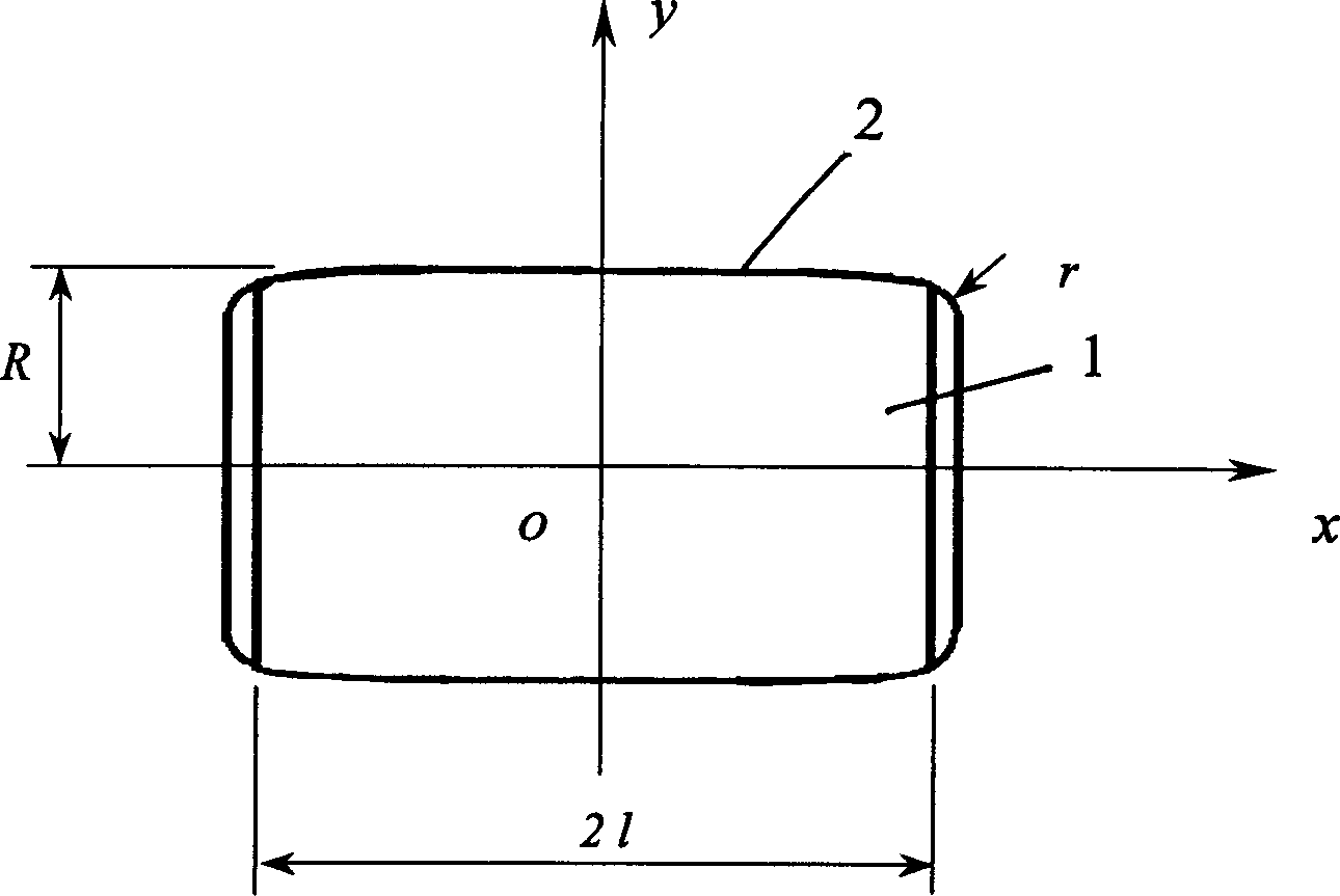
[0021] Such as figure 1 , figure 2 As shown, the shape of the busbar 2 of the bearing surface of the cylindrical roller 1 of the present invention is composed of a symmetrical logarithmic curve from the middle to both sides. The logarithmic curve is slightly raised in the middle of the busbar 2 and slowly decreases to both sides. The two ends of the logarithmic curve generatrix are smoothly connected with two chamfered arcs.

[0022] The logarithmic curve is:

[0023] y = R - K ln 1 ( 1 - ( x l ) 2 ) - - ...


PUM


Abstract

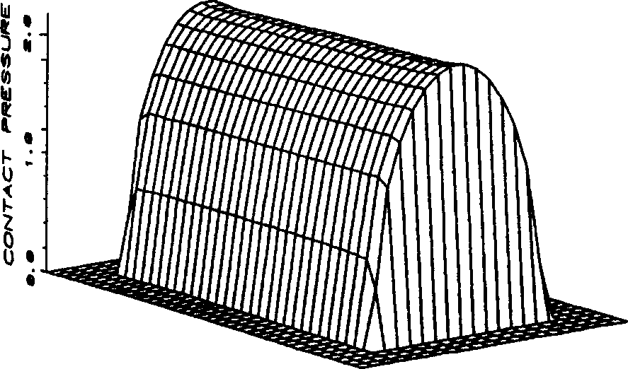
The invention relates to a logarithmic cylinder roller, whose generatrix of support surface is a logarithmic curve. The middle of said generatrix is protruded and two ends of generatrix are connected to two chamfering arc. The invention can eliminate the edge effect in the contact of cylinder roller to uniform distribute the contact pressure along the axes and improve the bearing ability and rigidity of roller contact couple, and the end part of cylinder roller can form a lubricate film to reduce the friction and abrasion in rolling. The better lubricate property can reduce the vibration and noise, improve the stability, improve the bearing ability and the application for worse working condition. The invention can apply the rolling needle too and other linear contact mechanics elements.

Description

technical field [0001] The invention relates to parts of rolling bearings, in particular to an engineering logarithmic cylindrical roller. Background technique [0002] In cylindrical roller bearings and needle roller bearings, the technical scheme of cylindrical roller and needle roller bearing surfaces generally adopts cylindrical surfaces, the generatrices are straight lines, and both ends are chamfered. Under load, the edge effect causes serious stress concentration at both ends of the roller, and no lubricating oil film can be formed between the roller and the bearing raceway. The sharp stress peak and direct contact between the metals cause material wear and fatigue spalling. When there is an installation error or deformation of related parts, there will be deflection between the roller and the bearing raceway, and the stress concentration will be more serious. The existing problems are: low load bearing capacity, severe friction and wear, large vibration, high noise,...

Claims


Application Information

Patent Timeline
IPC IPC(8): F16C33/36
Inventor 马家驹陈晓阳
Owner HANGZHOU LOGROLE BEARING & ROLLER
Learn More