
Method for regulating pressure of dresser in chemical mechanical polishing

A technology of pressure regulation and chemical machinery, applied in the direction of abrasive surface regulation devices, grinding machine parts, grinding/polishing equipment, etc., can solve the problem of affecting the mechanical grinding and manufacturing of silicon wafers, affecting the global planarization of wafers, and affecting costs and other problems, to achieve the effect of eliminating the edge effect phenomenon, eliminating the excessive consumption of the edge, and increasing the service life

Inactive Publication Date: 2020-08-04
长春长光圆辰微电子技术有限公司
View PDF8 Cites 2 Cited by
  • Summary
  • Abstract
  • Description
  • Claims
  • Application Information

AI Technical Summary

Problems solved by technology

The reason is that when the dresser moves to the edge of the polishing pad, the pressure exerted by the dresser remains unchanged, but the force-bearing area between the polishing pad and the dresser decreases, resulting in an increase in the pressure on the polishing pad and a decrease in the consumption of the polishing pad. Large, after a long time, there is a difference in the thickness of the middle part and the edge part of the polishing pad
Since the polishing pad as a consumable affects the cost of manufacturing and processing, it also affects the mechanical grinding and manufacturing of silicon wafers, which affects the effect of achieving global planarization of the wafer.

Method used


Image

  • Method for regulating pressure of dresser in chemical mechanical polishing
  • Method for regulating pressure of dresser in chemical mechanical polishing
  • Method for regulating pressure of dresser in chemical mechanical polishing

Examples


Embodiment Construction

[0023] In order to illustrate the present invention more clearly, the present invention will be further described below in conjunction with preferred embodiments. It should be understood by those skilled in the art. The content specifically described below is illustrative rather than restrictive. Users can make various changes to the following parameters without departing from the mechanism and scope of the invention set forth in the claims. In order not to obscure the essence of the present invention, well-known methods and procedures have not been described in detail.

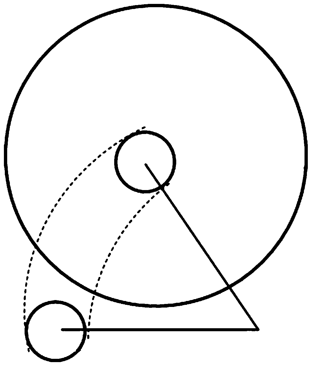
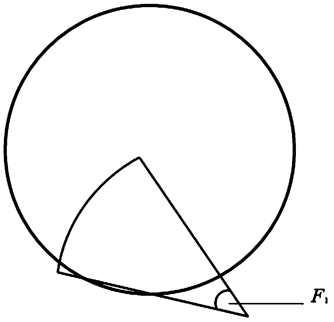
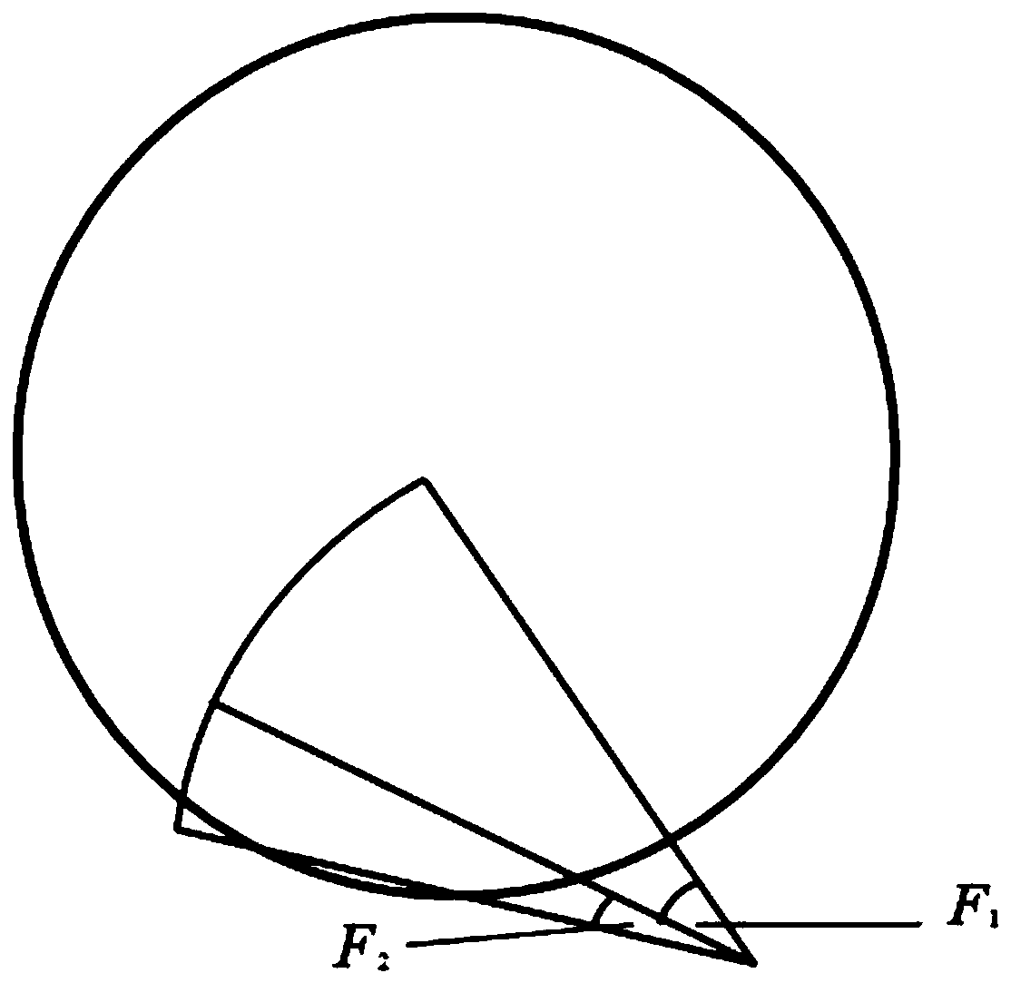
[0024] figure 1 The walking path of the dresser on the grinding pad is shown; figure 2 Schematic diagram showing the pressure distribution of the dresser on the polishing pad before modification, F 1 Set parameters for constant; image 3 Shows the pressure distribution of the dresser on the polishing pad in different regions after the modification of the dresser pressure adjustment method in chemical mec...


PUM


Abstract

The invention discloses a method for regulating pressure of a dresser in chemical mechanical polishing, and belongs to the field of semiconductor chip processing and manufacturing. The method comprises the following steps of, in the whole motion path of the dresser, dividing pressure control into two parts, and distinguishing according to the contact area of the dresser and a polishing pad: (1) when the dresser is in complete contact with the polishing pad, the pressure applied to the polishing pad by the dresser is F1, wherein F1 is preset constant pressure; and (2) during incomplete contact,the pressure applied to the polishing pad by the dresser is F2, and F2 changes along with the change of the contact area between the dresser and the polishing pad, so that all regions of the polishing pad are subjected to the same dressing pressure intensity. By means of the method for regulating the pressure of the dresser in chemical mechanical polishing, the edge effect phenomenon that the edge of the polishing pad is consumed too fast can be eliminated, the thickness difference between the middle part and the edge part of the polishing pad is improved, and the service life of the polishing pad is prolonged.

Description

technical field [0001] The invention relates to a method for adjusting the pressure of a dresser in chemical mechanical grinding, and belongs to the field of semiconductor chip processing and manufacturing. Background technique [0002] In the field of semiconductor chip processing and manufacturing, with the upgrading of process technology, photolithography technology has higher and higher requirements for the flatness of the wafer surface. The combination of chemical etching and mechanical grinding is currently the only technology that can achieve global planarization of the surface. In the process of chemical mechanical polishing, the wafer is in close contact with the polishing pad and a certain pressure is applied for relative movement. During this process, the roughness of the polishing pad and the overall shape change have a great impact on the polishing rate and flatness. In order to ensure that the mechanical removal rate of the wafer is stable and constant, it is ...

Claims


Application Information

Patent Timeline
IPC IPC(8): B24B53/017B24B53/12B24B49/00B24B51/00
CPCB24B49/00B24B51/00B24B53/017B24B53/12
Inventor 刘耀聪
Owner 长春长光圆辰微电子技术有限公司
Learn More