Friction weld coaxial connector and interconnection method

a technology of friction welding and coaxial connectors, which is applied in the direction of insulation conductors/cables, conductors, manufacturing tools, etc., can solve the problems of complex manufacturing and installation, and the interconnection may be less than satisfactory

Active Publication Date: 2012-11-06
COMMSCOPE TECH LLC
View PDF27 Cites 17 Cited by
  • Summary
  • Abstract
  • Description
  • Claims
  • Application Information

AI Technical Summary

Benefits of technology

[0026]Aluminum has been applied as a cost-effective alternative to copper for the conductors in coaxial cables. However, aluminum oxide surface coatings quickly form upon air-exposed aluminum surfaces. These aluminum oxide surface coatings may degrade traditional mechanical, solder and / or conductive adhesive interconnections.
[0034]An overbody 30, as shown for example in FIG. 10, may be applied to the connector body 4 as an overmolding of polymeric material. The overbody 30 increases cable to connector torsion and pull resistance. The overbody 30 may also provide connection interface structure at the connector end 18 and further reinforcing support at the cable end 12, enabling significant reductions in the size of the connector body 4, thereby reducing overall material costs.
[0035]Depending upon the applied connection interface 31, demonstrated in the exemplary embodiments herein as a standard 7 / 16 DIN interface, the overbody 30 may be provided with an overbody flange 32 and longitudinal support ridges 34 for a coupling nut 36. The coupling nut 36 is retained upon the support ridges 34 at the connector end 18 by an overbody flange 32 and at the cable end 12 by a retention spur 38 provided on at least one of the support ridges 34. The retention spur 38 may be angled toward the connector end 18, allowing the coupling nut 36 to be placed over the cable 9 initially spaced away from the coaxial connector 2 during interconnection (see FIG. 1), but then allowing the coupling nut 36 to be passed over the retention spur 38 and onto the support ridges 34 from the cable end 12, to be thereafter retained upon the support ridges 34 by the retention spur(s) 38 (see FIG. 2) in close proximity to the connector interface 31 for connector to connector mating. The support ridges 34 reduce polymeric material requirements of the overbody 30 while providing lateral strength to the connector / interconnection 2 as well as alignment and retention of the coupling nut 36.
[0036]The overbody 30 may also extend from the connector end 18 of the connector body 4 to provide portions of the selected connector interface 31, such as an alignment cylinder 39 of the 7 / 16 DIN interface, further reducing metal material requirements of the connector body 4.
[0038]As best shown in FIG. 11, the cable end 12 of the overbody 30 may be dimensioned with an inner diameter friction surface 44 proximate that of the coaxial cable outer jacket 28, enabling polymeric friction welding between the overbody 30 and the outer jacket 28, as the connector body 4 and outer conductor, thereby eliminating the need for environmental seals at the cable end 12 of the connector / cable interconnection. During friction welding, the coaxial connector 2 is rotated with respect to the cable 9. Friction between the friction surface 44 and the outer diameter of the outer jacket 28 heats the respective surfaces to a point where they begin to soften and intermingle, sealing them against one another. To provide enhanced friction and allow voids for excess flow due to friction displacement and add key locking for additional strength, the outer jacket 28 and / or the inner diameter of the overbody 30 may be provided as a series of spaced apart annular peaks of a contour pattern such as a corrugation 46, as shown for example in FIG. 12, or a stepped surface 48, as shown for example in FIG. 13. Alternatively, the overbody 30 may be sealed against the outer jacket 28 with an adhesive / sealant or may be overmolded upon the connector body 4 after interconnection with the outer conductor 8, the heat of the injected polymeric material bonding the overbody 30 with and / or sealing against the outer jacket 28.
[0041]One skilled in the art will appreciate that the connector and interconnection method disclosed has significant material cost efficiencies and provides a permanently sealed interconnection with reduced size and / or weight requirements.

Problems solved by technology

Although this type of connector is typically removable / re-useable, manufacturing and installation is complicated by the multiple separate internal elements required, interconnecting threads and related environmental seals.
However, solder and / or adhesive interconnections may be difficult to apply with high levels of quality control, resulting in interconnections that may be less than satisfactory, for example when exposed to vibration and / or corrosion over time.

Method used


Image

  • Friction weld coaxial connector and interconnection method
  • Friction weld coaxial connector and interconnection method
  • Friction weld coaxial connector and interconnection method

Examples


Embodiment Construction

[0026]Aluminum has been applied as a cost-effective alternative to copper for the conductors in coaxial cables. However, aluminum oxide surface coatings quickly form upon air-exposed aluminum surfaces. These aluminum oxide surface coatings may degrade traditional mechanical, solder and / or conductive adhesive interconnections.

[0027]The inventors have recognized that increasing acceptance of coaxial cable with solid outer conductors of aluminum and / or aluminum alloy enables connectors configured for interconnection via friction welding between the outer conductor and a connector body which may also be cost effectively provided, for example, formed from aluminum and / or aluminum alloy.

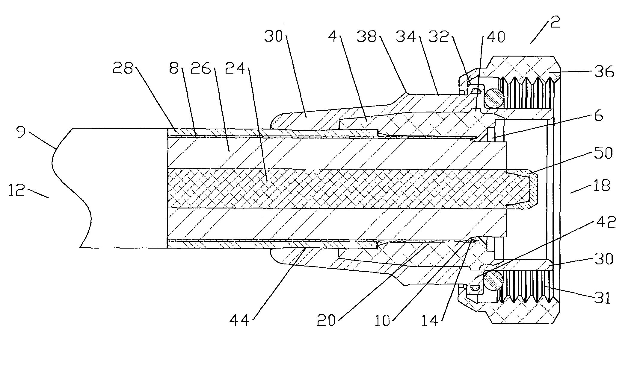
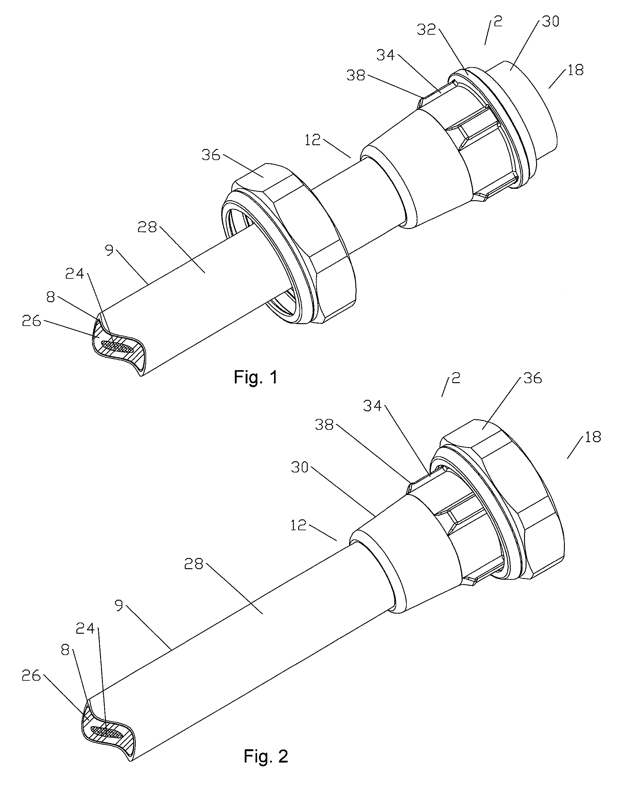
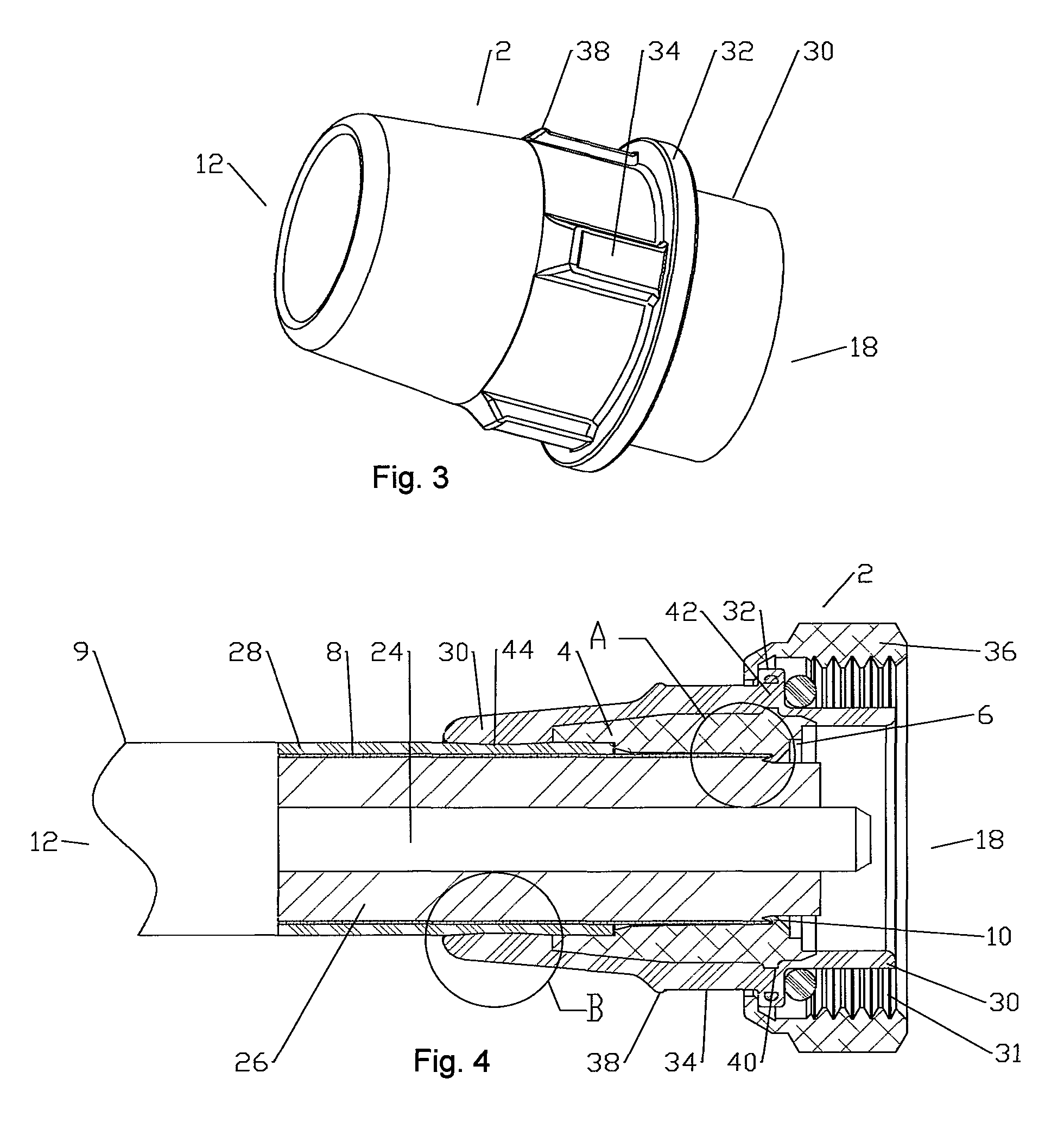
[0028]An exemplary embodiment of a friction weldable coaxial connector 2 is demonstrated in FIGS. 1-4. As best shown in FIG. 4, a unitary connector body 4 is provided with a bore 6 dimensioned to receive the outer conductor 8 of a coaxial cable 9 therein. An inward projecting shoulder 10 angled toward a ca...


PUM

PropertyMeasurementUnit
outer diameteraaaaaaaaaa
inner diameteraaaaaaaaaa
longitudinal forceaaaaaaaaaa

Abstract

A coaxial connector for interconnection with a coaxial cable with a solid outer conductor by friction welding is provided with a monolithic connector body with a bore. A sidewall of the bore is provided with an inward annular projection angled toward a cable end of the bore. A sidewall of the inward annular projection and the sidewall of the bore form an annular friction groove open to a cable end of the bore. The annular friction groove is dimensioned with a taper at a connector end of the friction groove less than a thickness of a leading end of the outer conductor. The taper provides an annular material chamber between the leading end of the outer conductor, when seated in the friction groove, and the connector end of the friction groove.

Description

CROSS REFERENCE TO RELATED APPLICATIONS[0001]This application is a continuation-in-part of commonly owned co-pending U.S. Utility patent application Ser. No. 12 / 951,558, titled “Laser Weld Coaxial Connector and Interconnection Method”, filed Nov. 22, 2010 by Ronald A. Vaccaro, Kendrick Van Swearingen, James P. Fleming, James J. Wlos and Nahid Islam, currently pending and hereby incorporated by reference in its entirety.BACKGROUND[0002]1. Field of the Invention[0003]This invention relates to electrical cable connectors. More particularly, the invention relates to a coaxial cable connector interconnectable via friction welding.[0004]2. Description of Related Art[0005]Coaxial cable connectors are used, for example, in communication systems requiring a high level of precision and reliability.[0006]To create a secure mechanical and optimized electrical interconnection between the cable and the connector, it is desirable to have generally uniform, circumferential contact between a leading...

Claims


Application Information

Patent Timeline
Patent Type & Authority Patents(United States)
IPC IPC(8): H01B13/20
CPCB23K20/129H01R4/029H01R9/05H01R43/0207H01R43/20B23K2201/38Y10T29/49123Y10T29/53235Y10T29/53209Y10T29/53Y10T29/53213Y10T29/532Y10T29/5313B23K2101/38
Inventor VAN SWEARINGEN, KENDRICK
Owner COMMSCOPE TECH LLC
Why Eureka
Try Eureka