
Molded ophthalmic lens

a molded, ophthalmic technology, applied in the field of ophthalmic lenses, can solve the problems that the clinic may not be able to perform procedures, and achieve the effects of large volume production, reduced production cost, and improved clear apertur

Active Publication Date: 2012-11-06
KATENA PROD
View PDF3 Cites 9 Cited by
  • Summary
  • Abstract
  • Description
  • Claims
  • Application Information

AI Technical Summary

Benefits of technology

The molded ophthalmic lens enables high-volume, low-cost production with enhanced optical quality, reducing the need for lens manipulation and allowing for quicker eye examinations and expanded procedural capabilities.

Problems solved by technology

Moreover, because of the larger clear aperture, the clinician may perform procedures not possible with a conventional ophthalmic lens.

Method used


Image

  • Molded ophthalmic lens
  • Molded ophthalmic lens
  • Molded ophthalmic lens

Examples


Embodiment Construction

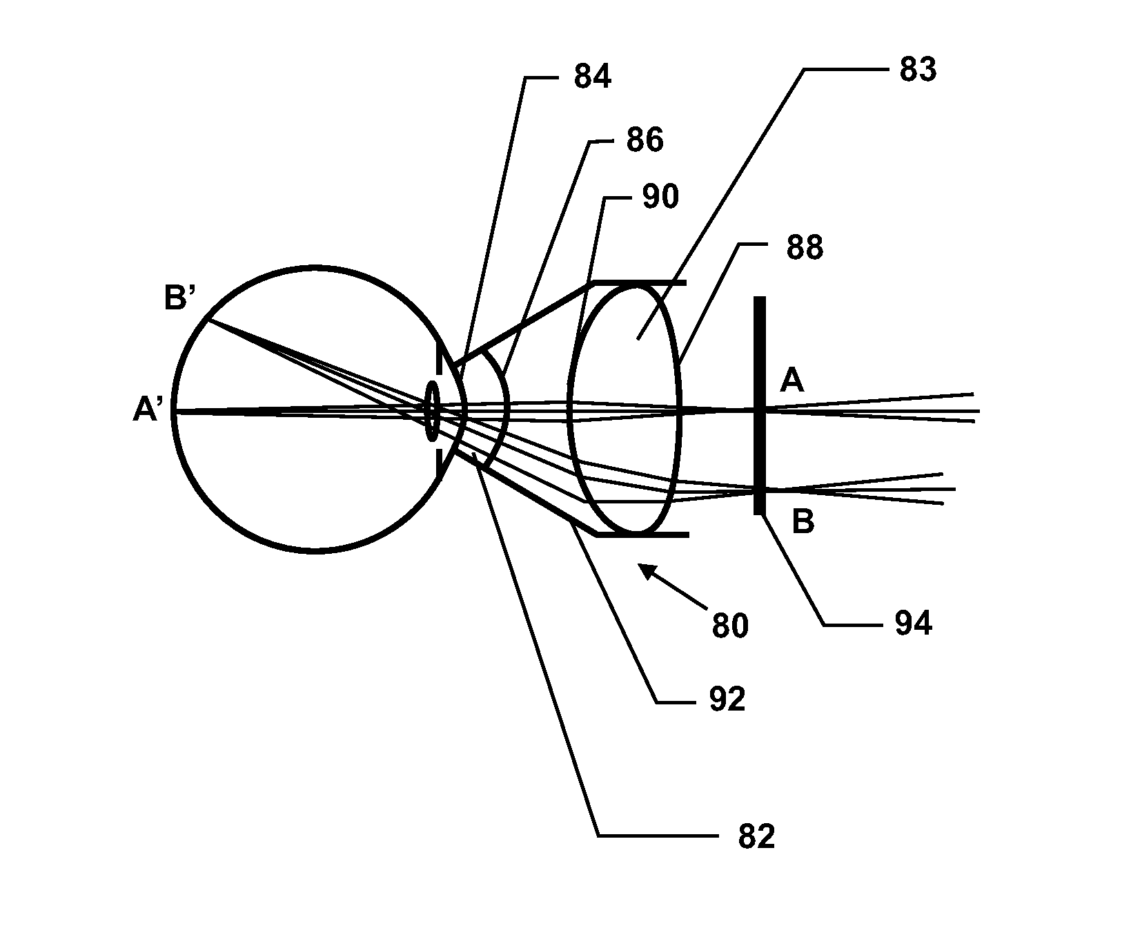
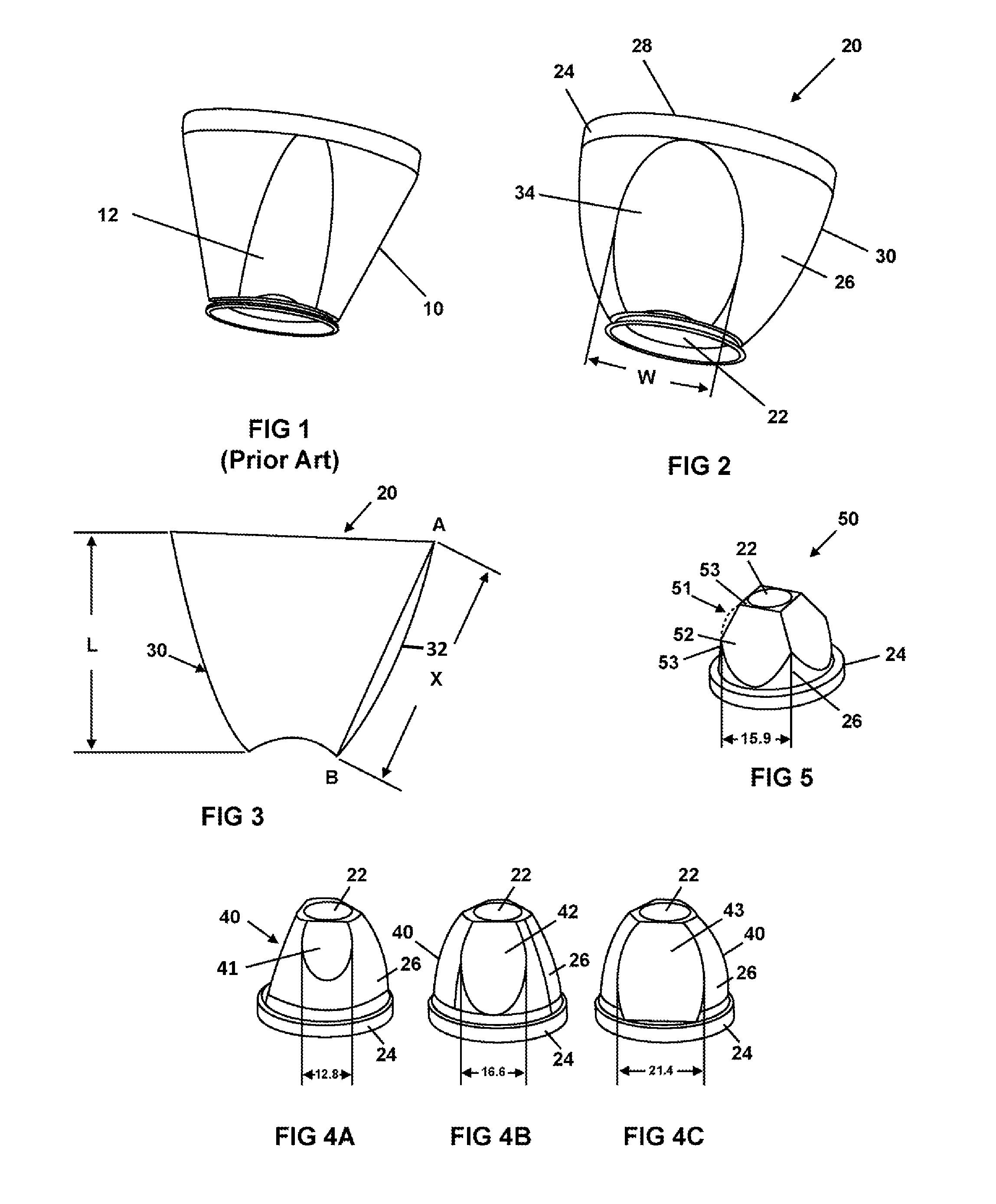
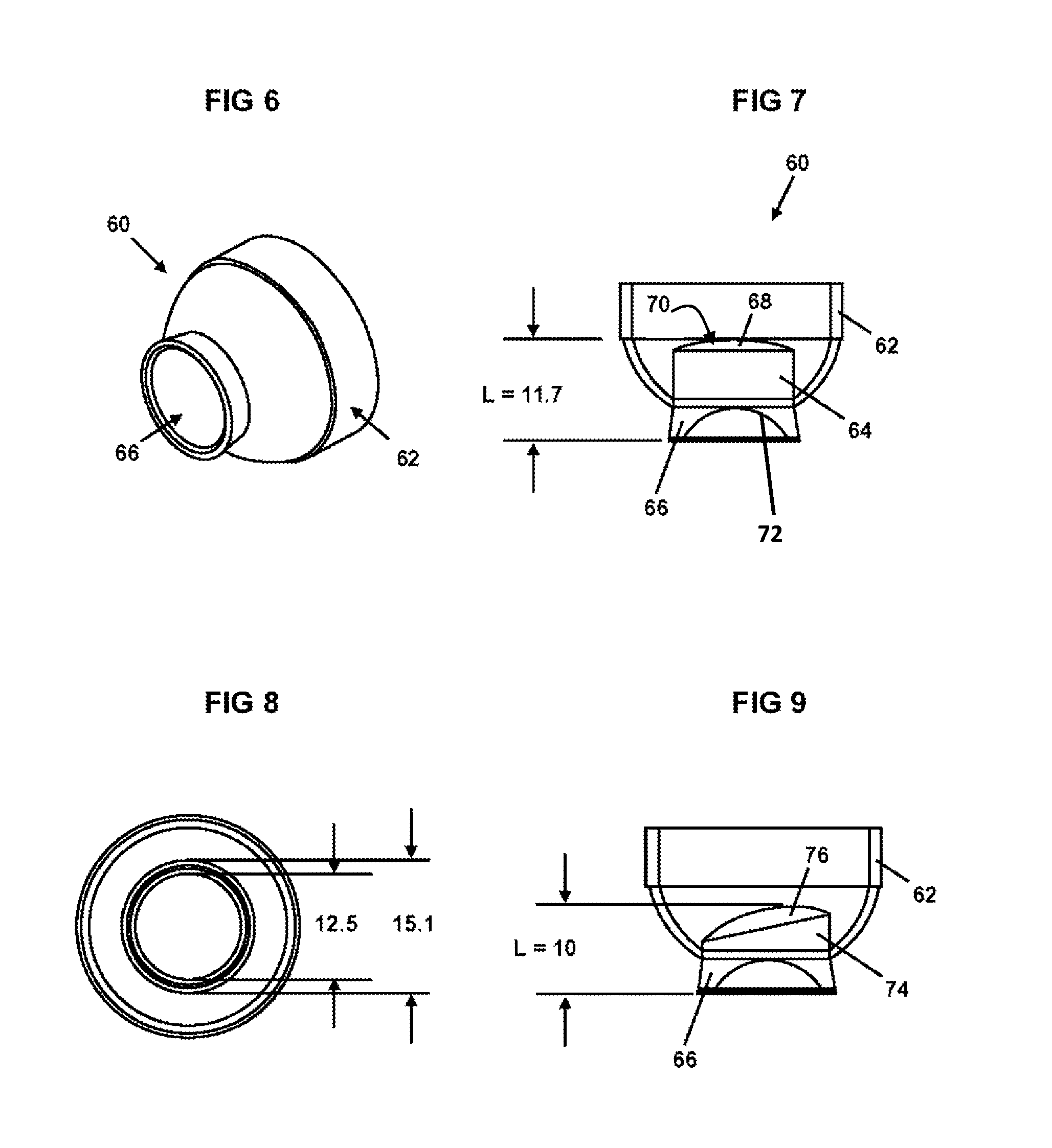
[0023]An ophthalmic lens 20 in accordance with one embodiment of the present invention, as shown in FIG. 2, has an eye contacting portion 22, a grip portion 24 and a main body portion 26 disposed between the eye contacting portion 22 and the grip portion 24. The eye contacting portion 22 of the ophthalmic lens 20 is shaped to match a cornea of an eye. In a preferred embodiment, the eye contacting portion of the lens has a diameter of approximately 12.5 mm and a radius curvature of 7.75 mm. The grip portion 24 of the ophthalmic lens 20 may have a generally cylindrical sidewall. In a preferred embodiment, the grip portion 24 is textured so that a clinician can easily maintain his grip on the lens 20 during diagnosis or treatment. It is noted that, if desired, a larger grip surface may be added over the grip portion 24. The surface 28 of the lens 20 opposite of the eye contacting portion 22 may be planar or curved for magnification.

[0024]The eye contacting portion 22, the main body por...


PUM


Abstract

An ophthalmic is injection molded and / or, compression molded to provide a single use lens. The ophthalmic lens has a larger clear aperture than known lenses of the same type to improve the optical quality of the lens.

Description

FIELD OF THE INVENTION[0001]The present invention relates to an ophthalmic lens and more particularly to a molded ophthalmic lens that has improved optical qualities and that can be manufactured in high volumes at low costs.CROSS-REFERENCE TO RELATED APPLICATIONS[0002]N / ASTATEMENT REGARDING FEDERALLY SPONSORED RESEARCH OR DEVELOPMENT[0003]N / ABACKGROUND OF THE INVENTION[0004]Ophthalmic lenses are used by ophthalmologists and optometrists for diagnosis and treatment of the eye. Known ophthalmic lenses as shown in FIG. 1 are machined to have a main body portion 10 with a conic shape and at least one mirror surface 12 in the optical path used by the clinician to view or treat the eye. Because known ophthalmic lenses are machined, they are extremely costly to manufacture and cannot be produced in high volumes.SUMMARY OF THE INVENTION[0005]In accordance with the present invention, the disadvantages of prior ophthalmic lenses have been overcome. The ophthalmic lens of the present invention...

Claims


Application Information

Patent Timeline
Patent Type & Authority Patents(United States)
IPC IPC(8): A61B3/10
CPCA61B3/125A61B3/117
Inventor HEACOCK, GREGORY LEE
Owner KATENA PROD
Learn More