Optical imaging lens

An optical imaging lens and lens technology, applied in the field of lenses, can solve the problems of low relative illumination at the edge of the imaging surface, low pixel value, blue-violet fringing, etc., and achieve good image color reproduction, high unit pixel ratio, and uniform relative illumination. Effect

Pending Publication Date: 2020-02-04
XIAMEN LEADING OPTICS
View PDF0 Cites 1 Cited by
  • Summary
  • Abstract
  • Description
  • Claims
  • Application Information

AI Technical Summary

Problems solved by technology

However, the optical imaging lenses currently used in intelligent transportation systems have a low ratio of unit pixels (pixels), which is not conducive to the development of later algorithms; the general light transmission is relatively small, and the relative illuminance at the edge of the imaging surface is low; the size of the

Method used


Image

  • Optical imaging lens
  • Optical imaging lens
  • Optical imaging lens

Examples


Embodiment 2

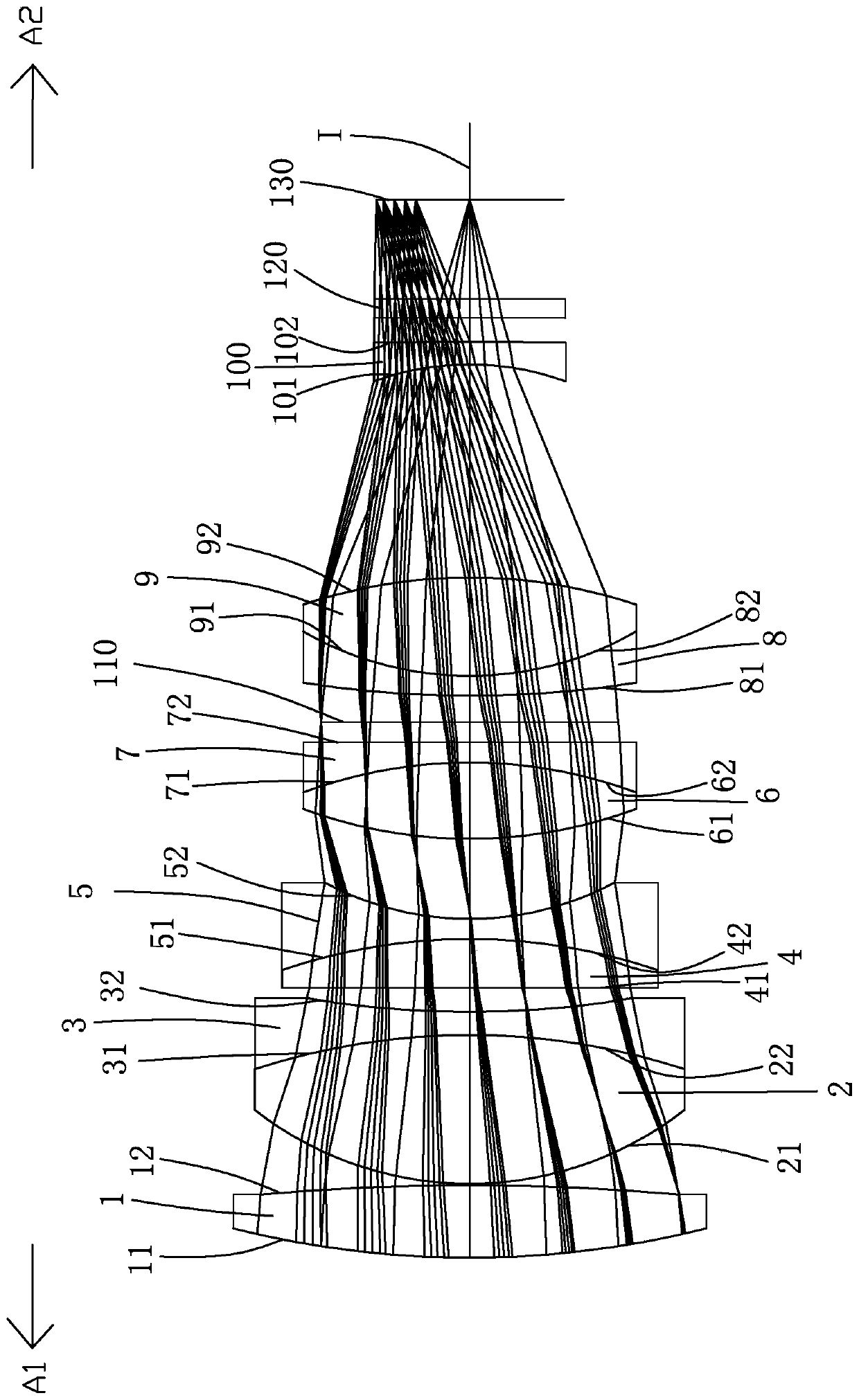
[0094] Such as Figure 7 As shown, the concave-convex surface shape and refractive power of each lens in this embodiment and the first embodiment are approximately the same, only the image side 102 of the tenth lens 100 is a convex surface, and the optical parameters such as the radius of curvature of each lens surface and lens thickness are also the same. different.

[0095] The detailed optical data of this specific embodiment are shown in Table 2-1.

[0096] Detailed optical data of Table 2-1 Example 2

[0097] surface Caliber / mm Radius of curvature / mm Thickness / mm material Refractive index Dispersion coefficient Focal length / mm - subject surface Infinity Infinity 11 first lens 44.000 84.844 6.734 H-BAK8 1.572499 57.5208 107.39 12 38.000 -220.102 0.134 21 second lens 40.000 33.236 15.010 FCD10A 1.458597 90.1949 51.19 22 40.000 -89.185 0 31 third lens 40.000 -...

Embodiment 3

[0101] Such as Figure 13 As shown, the concave-convex surface shape and refractive power of each lens in this embodiment and the first embodiment are approximately the same, only the image side 102 of the tenth lens 100 is a convex surface, and the optical parameters such as the radius of curvature of each lens surface and lens thickness are also the same. different.

[0102] The detailed optical data of this specific embodiment are shown in Table 3-1.

[0103] Detailed optical data of the third embodiment of table 3-1

[0104] surface Caliber / mm Radius of curvature / mm Thickness / mm material Refractive index Dispersion coefficient Focal length / mm - subject surface Infinity Infinity 11 first lens 44.000 84.561 6.970 H-BAK8 1.572499 57.5208 107.16 12 38.800 -220.052 0.131 21 second lens 40.000 33.270 15.063 FCD10A 1.458597 90.1949 51.18 22 40.000 -68.952 0 31 third ...

Embodiment 4

[0108] Such as Figure 19 As shown, this embodiment and the embodiment 1 have the same concave-convex surface shape and refractive index of each lens, and only the optical parameters such as the radius of curvature of each lens surface and lens thickness are also different.

[0109] The detailed optical data of this specific embodiment are shown in Table 4-1.

[0110] Table 4-1 Detailed optical data of Example 4

[0111] surface Caliber / mm Radius of curvature / mm Thickness / mm material Refractive index Dispersion coefficient Focal length / mm - subject surface Infinity Infinity 11 first lens 44.000 92.335 6.758 H-BAK8 1.572499 57.5208 106.64 12 39.000 -220.711 0.148 21 second lens 40.000 45.233 15.272 FCD10A 1.458597 90.1949 51.28 22 40.000 -81.374 0 31 third lens 40.000 -81.374 1.987 FD60-W 1.805181 25.4564 -48.50 32 28.657 77.268 2.078 41 ...


PUM


Abstract

The invention relates to the technical field of lenses, and discloses an optical imaging lens. The optical imaging lens comprises ten lenses. The first lens, the second lens, the sixth lens and the ninth lens are convexo-convex lenses with a positive refractive power, and the third lens and the fifth lens are concavo-concave lenses with a negative refractive index, the fourth lens is a plano-convex lens with the positive refractive index, the seventh lens is a concave-convex lens with the negative refractive index, the eighth lens is a convex-concave lens with the negative refractive index, and the tenth lens is a concavo-concave lens or concave-convex lens with the negative refractive index. The image side surface of the second lens and the object side surface of the third lens are gluedto each other; the image side surface of the fourth lens and the object side surface of the fifth lens are glued to each other; the image side surface of the sixth lens and the object side surface ofthe seventh lens are glued to each other; and the image side surface of the eighth lens and the object side surface of the ninth lens are glued to each other. The optical imaging lens has the advantages of a large image surface, a high ratio of unit pixel, large light transmission, good chromatic aberration optimization and good imaging quality.

Description

technical field [0001] The invention belongs to the field of lens technology, and in particular relates to an optical imaging lens used in an intelligent traffic system. Background technique [0002] With the continuous advancement of science and technology, in recent years, optical imaging lenses have also developed rapidly, and are widely used in various fields such as smart phones, tablet computers, video conferencing, vehicle monitoring, security monitoring, intelligent transportation systems, etc. Therefore, for optical The requirements for imaging lenses are also getting higher and higher. [0003] In intelligent transportation systems, the performance of optical imaging lenses is critical and will affect the reliability of the entire system. However, the optical imaging lenses currently used in intelligent transportation systems have a low ratio of unit pixels (pixels), which is not conducive to the development of later algorithms; the general light transmission is r...

Claims


Application Information

Patent Timeline
IPC IPC(8): G02B13/00
CPCG02B13/0015G02B13/006
Inventor 张军光黄波
Owner XIAMEN LEADING OPTICS
Why Eureka
Try Eureka