720° panoramic camera system

A panoramic camera and panoramic lens technology, which is applied in the field of 720° panoramic camera system, can solve the problems of geometrical improvement of lens assembly difficulty, deflection of optical path, and difficulty in carrying, etc. The effect of shortening the overall length

Active Publication Date: 2022-02-18
FOCTEK PHOTONICS INC
View PDF6 Cites 0 Cited by
  • Summary
  • Abstract
  • Description
  • Claims
  • Application Information

AI Technical Summary

Problems solved by technology

[0002] There are currently several 720° panoramic systems on the market. Most of the solutions are composed of more than two lenses with more than two chips. The disadvantage of the solution with more than two chips is that it requires more than two chip and digital signal processor, and then the images of the two chips are processed and stitched into a panoramic full-sky image
The disadvantage of this solution is that because the image is composed of two independent chips and digital signal processors, the system integration and setting are cumbersome and costly, and the two lenses need to be imaged synchronously, which increases the difficulty of the overall assembly of the lens geometrically. It is difficult to improve the assembly yield and efficiency, and the quality of batch products is not easy to guarantee.
What is especially serious is that the two processors are not synchronized, so when the system stitches the image screen, there will be a situation where the screen is missing, that is, there may be a situation where a person lacks arms and legs at a certain moment on the screen
Not conducive to marketing
More than three chip processing solutions are more cumbersome and costly
Although the stability and reliability of this solution have been greatly improved, and there will be no lack of arms or legs when splicing images, but because the lens is turned from the rear, the overall configuration of the system is relatively long. The system is an anti-telescopic structure, and the optical path is deflected outside the lens. There is not enough space to increase the IR-CUT structure. It is necessary to add a visible light spectrum and 940nm infrared spectrum dual-pass filter inside the lens to solve the problem of night use. The problem is that it is relatively difficult to carry

Method used


Image

  • 720° panoramic camera system
  • 720° panoramic camera system
  • 720° panoramic camera system

Examples


Embodiment Construction

[0043] The content of the present invention will be described in detail below in conjunction with the accompanying drawings and specific embodiments of the description:

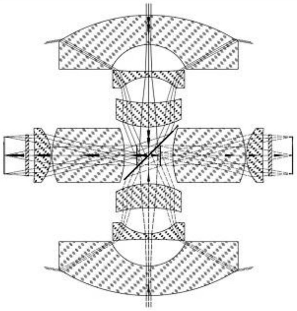
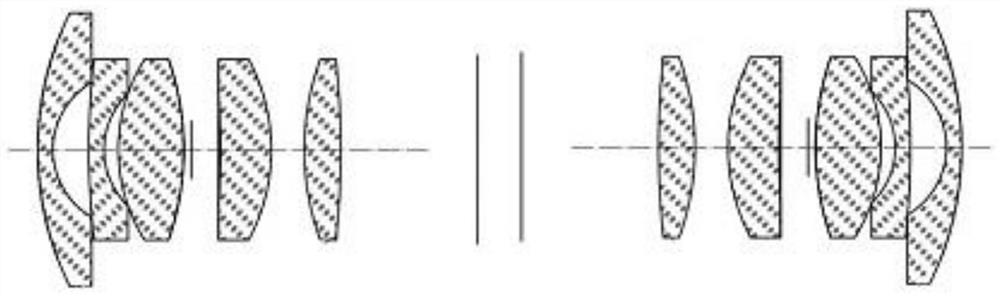
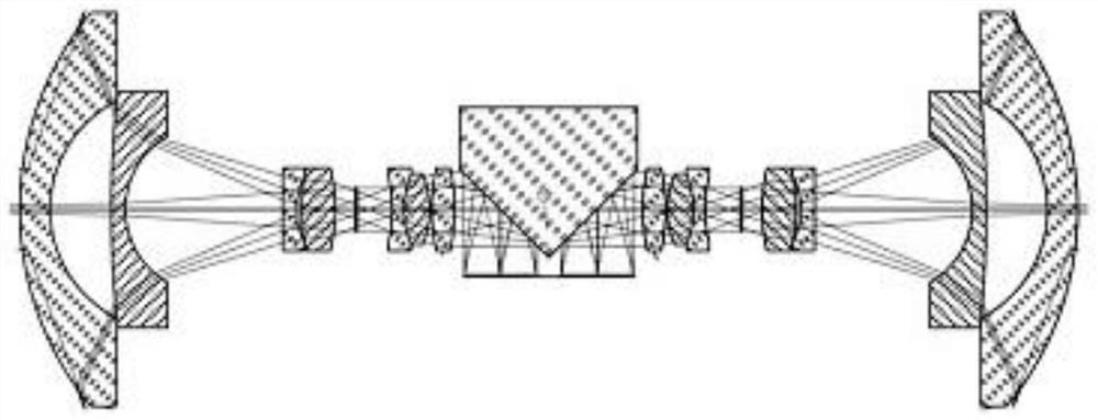
[0044] Such as Figure 4-5 As shown, a 720° panoramic camera system provided by the present invention is characterized in that it includes a sensor chip S9, a digital signal processor, an optical path deflection element, and two groups of panoramic lenses symmetrically arranged on both sides of the optical path deflection element , the optical path deflection element is arranged inside the two groups of panoramic lenses so as to deflect the optical paths of the two groups of panoramic lenses by 90°, and the sensor chip S9 is used to receive the deflected incident light rays of the two groups of panoramic lenses and convert the image The information is sent to the digital signal processor, and the digital signal processor generates a three-dimensional 720° panoramic image after splicing the image information o...


PUM


Abstract

The invention relates to the field of camera equipment, in particular to a 720° panoramic camera system, which includes a sensor chip, a digital signal processor, an optical path deflection element, and two sets of panoramic lenses symmetrically arranged on both sides of the optical path deflection element. The components are arranged inside the two sets of panoramic lenses to deflect the optical paths of the two sets of panoramic lenses by 90°. The sensor chip is used to receive the deflected incident light from the two sets of panoramic lenses and output the image information to the digital signal processor. The signal processor splices and processes the image information of the two sets of panoramic lenses to generate a three-dimensional 720° panoramic image. The field of view of each set of panoramic lenses is greater than 190° and the F-thera distortion is less than 9.5%. The effective rear of each set of panoramic lenses The focal length is greater than 5mm. The system not only shortens the overall length of the system and is easy to carry, but also can add an IR‑CUT structure at the rear of the lens to achieve day and night use.

Description

technical field [0001] The invention relates to the field of camera equipment, in particular to a 720° panoramic camera system. Background technique [0002] There are currently several 720° panoramic systems on the market. Most of the solutions are composed of more than two lenses with more than two chips. The disadvantage of the solution with more than two chips is that it requires more than two chip and digital signal processor, and then the images of the two chips are processed and stitched into a panoramic full-sky image. The disadvantage of this solution is that because the image is composed of two independent chips and digital signal processors, the system integration and setting are cumbersome and costly, and the two lenses need to be imaged synchronously, which increases the difficulty of the overall assembly of the lens geometrically. The assembly yield and efficiency are difficult to improve, and the quality of batch products is not easy to guarantee. What is es...

Claims


Application Information

Patent Timeline
Patent Type & Authority Patents(China)
IPC IPC(8): G03B37/04G02B17/04
CPCG02B17/04G03B37/04
Inventor 黄木旺黄统樑罗联镜陆鹏邱滨滨
Owner FOCTEK PHOTONICS INC
Why Eureka
Try Eureka