
High voltage subsea electrical penetrator

a technology of electrical penetrators and subsea water, which is applied in the direction of sealing/packing, coupling device connections, and well accessories, etc., can solve the problems of local tensile and shear stresses in the insulator body material, the limit of allowable nominal and differential pressures over the bushing, and the associated higher production costs. achieve the effect of maximum utilization of material properties

Active Publication Date: 2012-11-06
VETCO GRAY SCANDINAVIA
View PDF11 Cites 10 Cited by
  • Summary
  • Abstract
  • Description
  • Claims
  • Application Information

AI Technical Summary

Benefits of technology

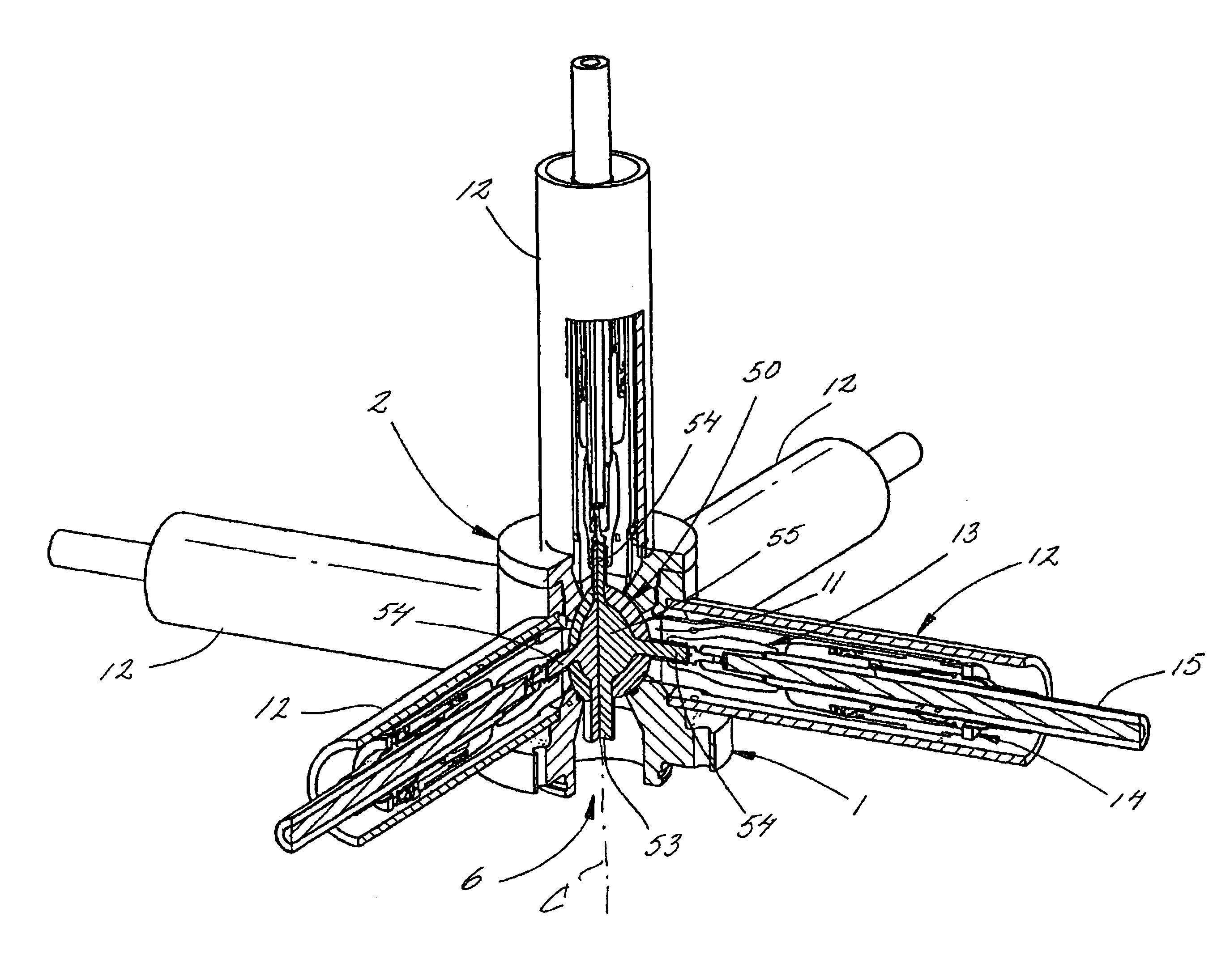
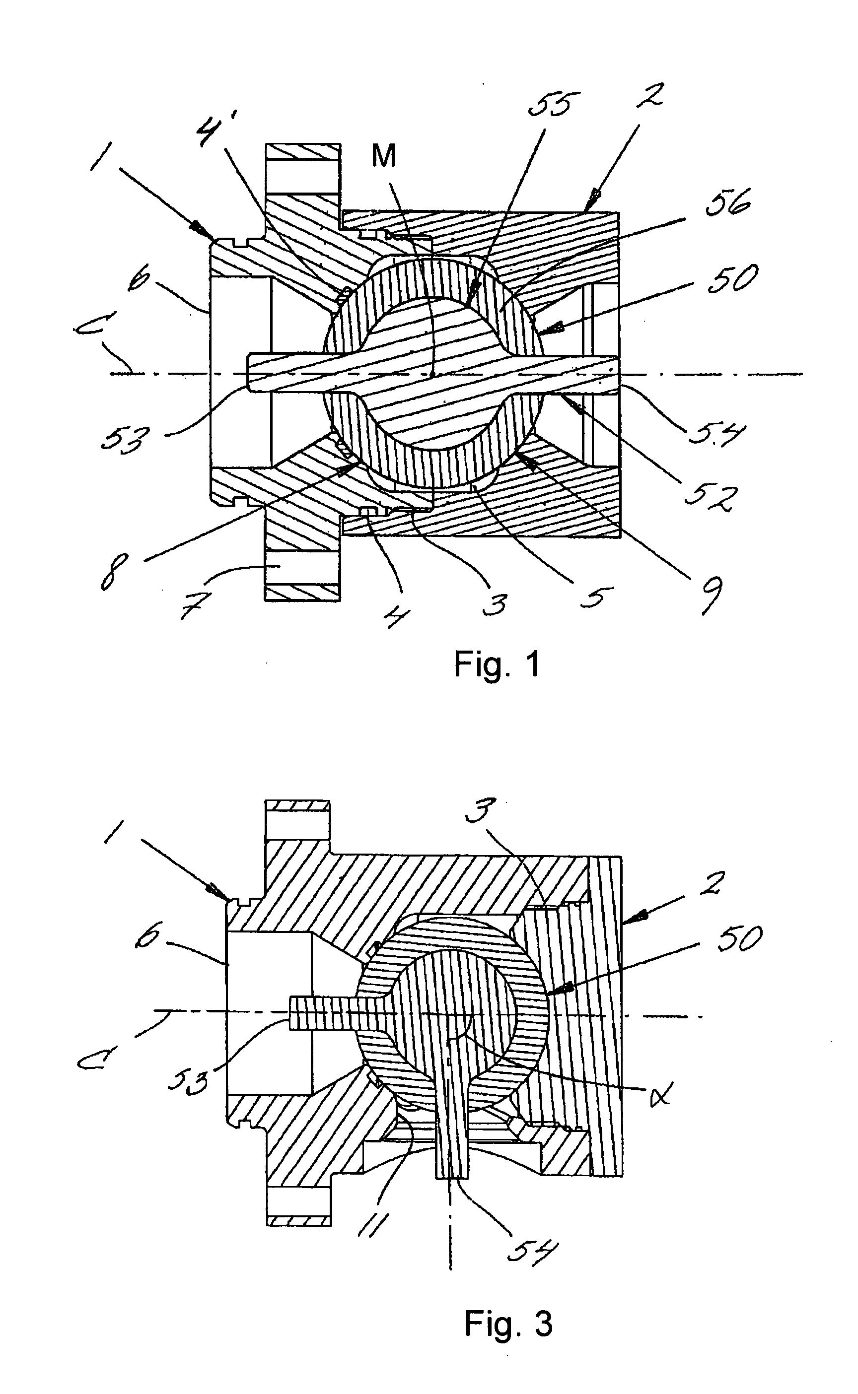
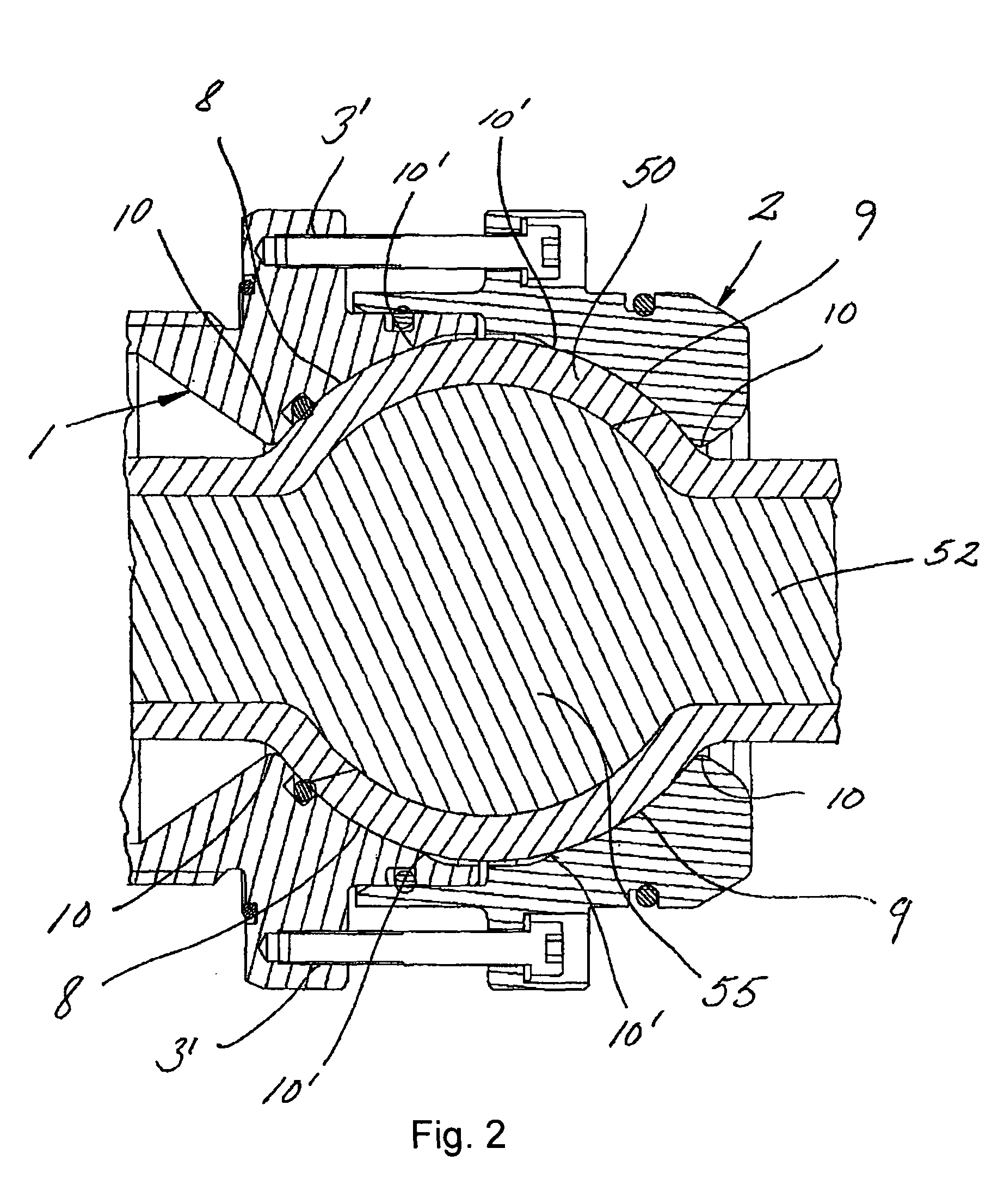
The present invention provides a subsea electrical penetrator that can operate at increased ambient and differential pressure ranges. The penetrator includes a housing with a seat for a bushing, which is made of a high-strength material such as polymer or ceramic. The bushing is securely sealed to the housing using a seal element, such as an O-ring or a seal formed by molding the seat surfaces of the housing parts. The insulator body is molded around the conductor pin and is designed to seal with the conductor pin and the housing. The penetrator can be assembled using a threaded connection between the housing parts and can be grounded and coated for better load distribution and sealing. The insulator body is made of a polymer material, which is cost-effective and easy to manufacture. The patent text also describes different embodiments of the subsea electrical penetrator, including an axial and angular configuration.

Problems solved by technology

At higher pressures, the angular transitions into the slanting surfaces on the insulator body and on the penetrator housing respectively however induces local tensile and shear stresses in the insulator body material, and sets a limit for allowable nominal and differential pressures over the bushing.
Other penetrator designs having ceramic or glass insulator bodies may be structured to withstand higher pressures, but suffer from a more complex production and associated higher production costs.
Albeit the structure of the device disclosed in RU 2050651 C1 is readable on the preamble of claim 1 of the present invention, it is acknowledged that the device disclosed in RU 2050651 C1 is however less suitable for the purpose of conducting electric current at high voltages where high differential pressures are prevailing, due to the limited yield strength of an elastomeric material and due to the limited thickness of the injection moulded polymer insulation which is available through the dimension of the gap that is formed between the conductor element and its seat.

Method used


Image

  • High voltage subsea electrical penetrator
  • High voltage subsea electrical penetrator
  • High voltage subsea electrical penetrator

Examples


Embodiment Construction

AND PREFERRED EMBODIMENTS OF THE INVENTION

[0037]In the following specification, the expression spherical shall be understood in a broader sense to include rotationally symmetric rounded shapes such as egg-shapes, spheroids, substantially true spheres and true spheres, all of which have a rounded shape in this case for the purpose of substantially avoiding or limiting tensile stresses caused by body shape and / or body distortion under load. The expression part-spherical shall be understood as referring to a region of such a spherical shape, such as a semi-spherical region, or a continuous or non-continuous ring-shaped region of a sphere.

[0038]It need not be a requisite to benefit from the invention, but considered a most advantageous case, when the spherical shapes of the insulator body and seat surfaces of the present invention are formed axially symmetric with respect to a longitudinal axis. The expression axially symmetric shall in this connection be understood to specify a conditi...


PUM


Abstract

A high voltage subsea electrical penetrator. A first housing part is connectable to a second housing part. The first and second housing parts in connected mode define a seat for accommodation of a bushing including a conductor pin arranged in an insulator body. The first and second housing parts each have a part-spherical seat surface supporting a corresponding region of the bushing. The bushing includes a material of relatively high compressive strength, in the form of a polymeric material or a ceramic material, that is molded into spherical outer shape about a bulbous portion of the conductor pin, and clamped as a unitary form-fitting element in the seat upon connection of the first and second housing parts.

Description

CROSS-REFERENCE TO RELATED APPLICATIONS[0001]This application claims priority under 35 U.S.C. §119 to Norwegian patent application 20085312 and is the national phase under 35 U.S.C. §371 of PCT / EP2009 / 007831 filed 18 Dec. 2009.TECHNICAL FIELD OF THE INVENTION[0002]The present invention relates to a high voltage subsea electrical penetrator having a bushing, the bushing comprising a conductor pin embedded in an insulator body and arranged to be mounted in a penetrator housing.BACKGROUND AND PRIOR ART[0003]In subsea production, electrically operated apparatuses below sea level are typically supplied by power from sea- or land-based host facilities. Operating power, in this connection typically at voltages of 1 kV and above, is conducted via cable conductors to submerged process control equipment, pumps and compressors, transformers, motors, and other electrically operated equipment, and is introduced to encapsulated power consumers by means of a cable termination and connector, in thi...

Claims


Application Information

Patent Timeline
Patent Type & Authority Patents(United States)
IPC IPC(8): H01H41/00
CPCH01R13/523H01R13/53H02G15/14H01B17/30
Inventor RAAD, ERIKSLETTEN, RUNE
Owner VETCO GRAY SCANDINAVIA
Learn More