
Multistage electrolytic cell

An electrolytic cell and cell body technology, applied in the field of electrolytic cells, can solve the problems of long service time, poor safety, and many hazardous waste leakage points, and achieve the effects of accurately controlling the electrolysis rate, increasing the pressure range, and ensuring safe operation.

Active Publication Date: 2020-04-03
XIAN UNITED PRESSURE VESSEL CO LTD
View PDF12 Cites 1 Cited by
  • Summary
  • Abstract
  • Description
  • Claims
  • Application Information

AI Technical Summary

Problems solved by technology

The traditional electrolyzer has poor corrosion resistance, and only has a temperature measuring device without a temperature control device, which has great limitations in use and high requirements on the surrounding environment.
Each level of the drain port at the bottom of the tank needs to be set up with a separate valve to control the drain port. There are many hazardous waste leakage points, and the bottom is not suitable for maintenance and investigation.
Due to the large number of electrode plates in the electrolytic cell and the short distance, the distance deviation between the traditional electrode plates is large, and the depth of the tank is generally large. It is easy to cause a short circuit of the electrode plates during installation and use, and there are many electrode connection covers, and the positioning accuracy is poor.
Moreover, due to the special working conditions of the electrolytic cell, the service time is long, and the slight shaking of the electrode is also easy to contact the wall plate, electrode and partition of the electrolytic cell, resulting in a short circuit, and the pipelines are not connected by insulation, which is poor in safety.

Method used


Image

  • Multistage electrolytic cell
  • Multistage electrolytic cell
  • Multistage electrolytic cell

Examples


Embodiment Construction

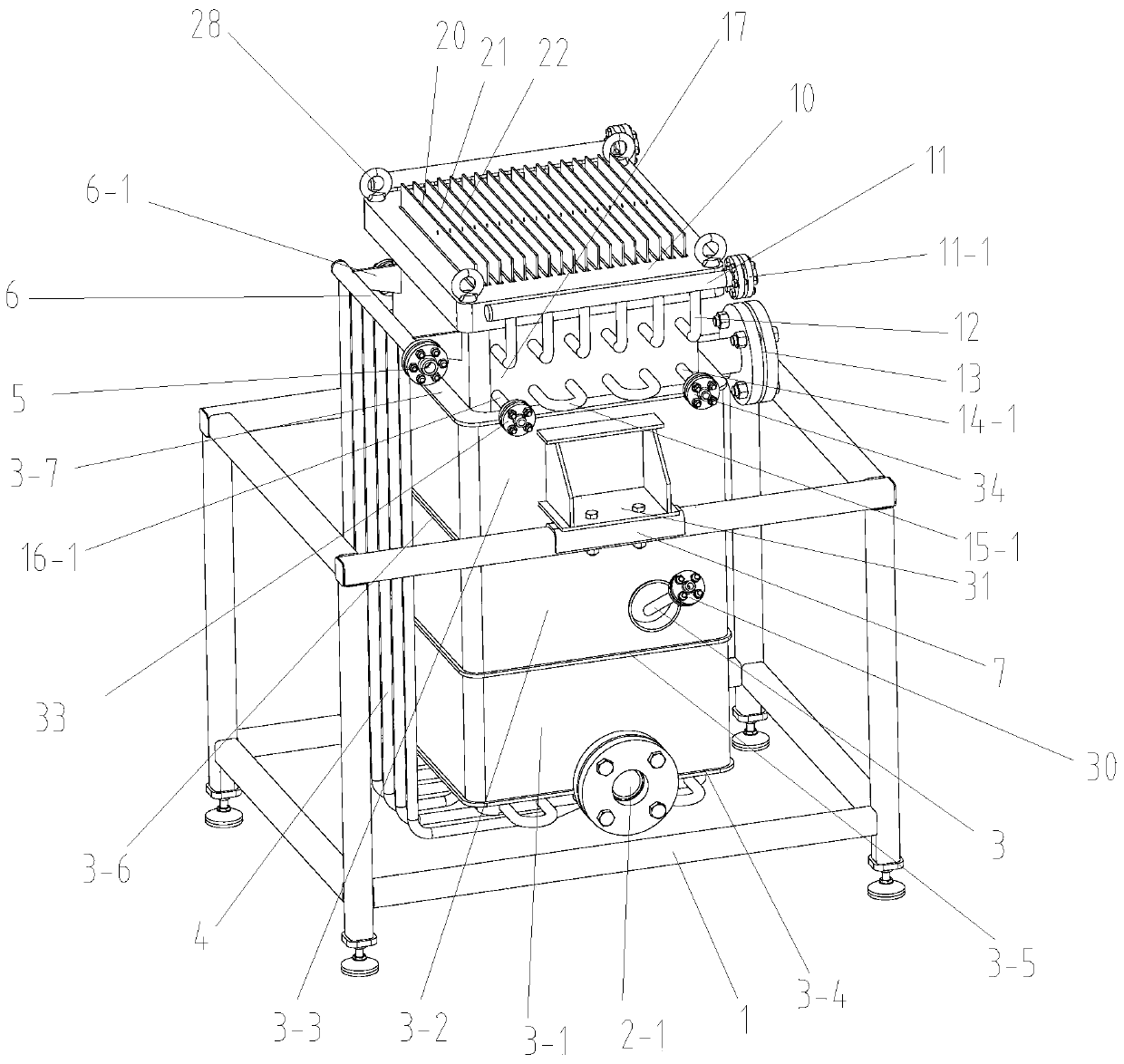
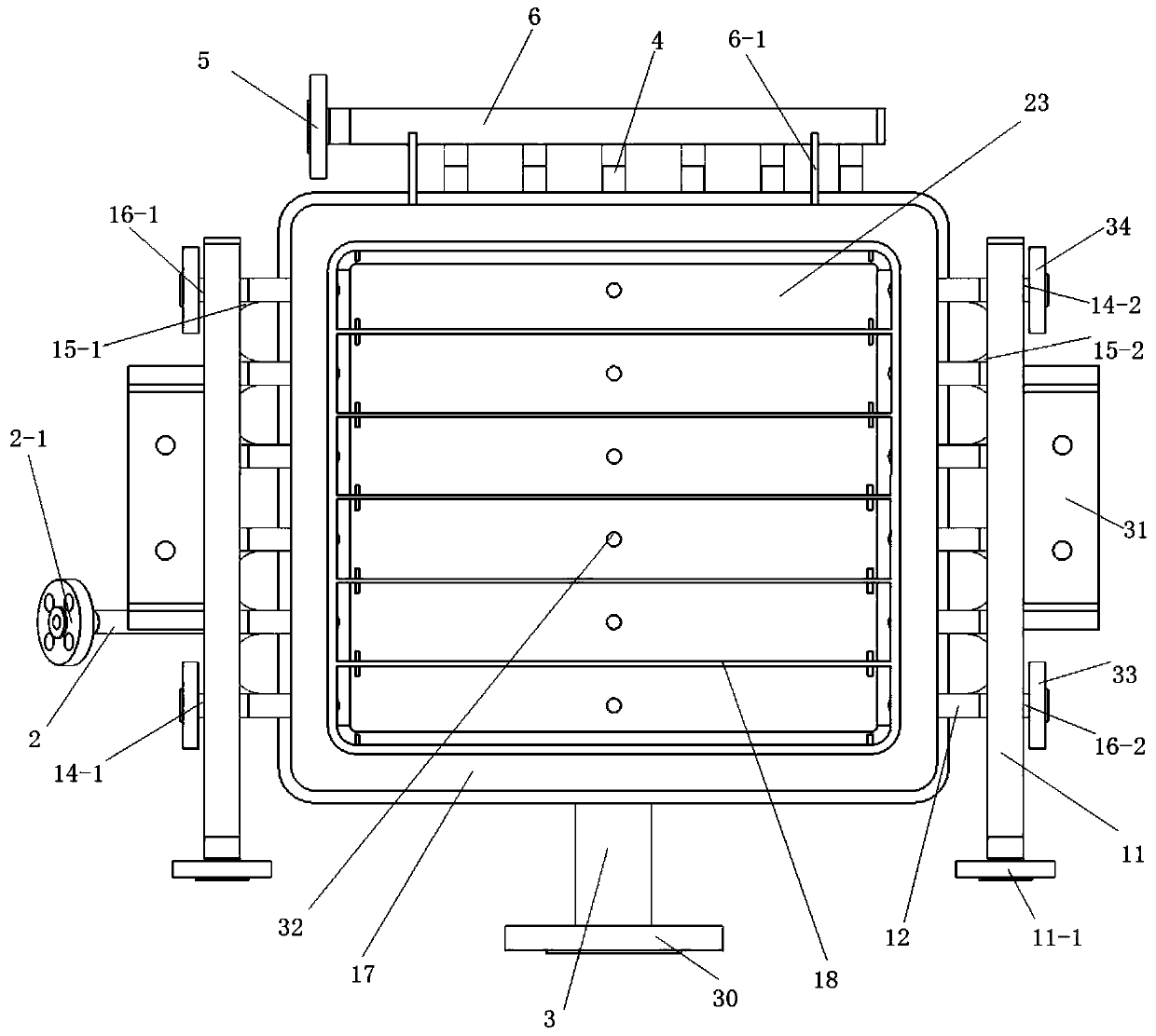
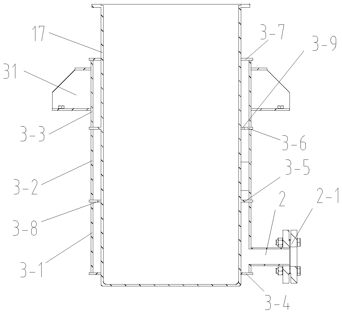
[0074] Such as figure 1 and figure 2 A kind of multistage electrolytic cell shown, comprises support 1, the electrolytic cell mechanism that is arranged on the support 1 and the cooling mechanism that surrounds on described electrolytic cell mechanism, and described electrolytic cell mechanism comprises cell body 17, two and The liquid inlet and outlet parts connected to the tank body 17, two exhaust parts connected to the tank body 17 and the sucking liquid part connected to the bottom of the tank body 17, and the cover plate 10 arranged on the top of the tank body 17, the tank body 17 A plurality of partitions 18 are arranged inside, and the partition 18 divides the inner cavity of the tank body 17 into a plurality of electrolytic cells 23, and the number of the electrolytic cells 23 is an even number;

[0075] The two liquid inlet and outlet parts are respectively the first liquid inlet and outlet parts arranged on one side of the tank body 17 and the second liquid inlet ...


PUM


Abstract

The invention discloses a multistage electrolytic cell. The multistage electrolytic cell comprises a support, an electrolytic cell mechanism and a cooling mechanism, the electrolytic cell mechanism comprises a cell body, a liquid inlet and outlet part, an exhaust part, a liquid suck-back part and a cover plate, a plurality of partition plates are arranged in the cell body, the partition plates divide an inner cavity of the cell body into a plurality of electrolytic cells, an electrode plate mechanism, flow guide mechanisms symmetrically arranged at the two ends of the electrode plate mechanismand a locking mechanism for positioning the electrode plate mechanism are arranged in each electrolytic cell, and the cover plate is provided with a plurality of positioning grooves for the electrodeplate mechanisms to be inserted. The device is simple in structure, reasonable in design, low in cost, convenient to install and use and high in material corrosion resistance, the cooling mechanism is arranged to regulate the electrolysis temperature, the flow guide mechanism is arranged to enable the electrolysis rate to be uniform, the locking mechanism is arranged to isolate the multiple electrode plates and completely isolate the multiple electrode plates from electrolytic cell wall plates, short circuit of the electrode plates is avoided, and safety and reliability are high.

Description

technical field [0001] The invention belongs to the technical field of electrolytic cells, and in particular relates to a multistage electrolytic cell. Background technique [0002] The electrolyzer is mainly used to prepare qualified uranium-containing solution and provide reducing agent to other systems. The traditional electrolyzer has poor corrosion resistance, and only has a temperature measuring device without a temperature control device, which has great limitations in use and high requirements on the surrounding environment. Each level of the drain port at the bottom of the tank needs to be set up with a separate valve to control the drain port. There are many hazardous waste leakage points, and the bottom is not suitable for maintenance and investigation. Due to the large number of electrode plates in the electrolytic cell and the short distance, the distance between the traditional electrode plates has a large deviation, and the depth of the tank is generally larg...

Claims


Application Information

Patent Timeline
IPC IPC(8): C25B9/18C25B9/00C25B15/00C25B15/08
CPCC25B9/00C25B15/00C25B15/08C25B9/70
Inventor 童路孙万仓贺旭明张成王娅辉崔少平段飚王王海波
Owner XIAN UNITED PRESSURE VESSEL CO LTD
Learn More