Imaging polarimeter

a polarimeter and imaging technology, applied in the field of imaging polarimeters, can solve the problems of noisy data, difficult registration, and polarimeters that have not utilized rigid monolithic beam splitters

Active Publication Date: 2012-11-06
LOCKHEED MARTIN CORP
View PDF2 Cites 20 Cited by
  • Summary
  • Abstract
  • Description
  • Claims
  • Application Information

AI Technical Summary

Problems solved by technology

However, polarimeters have not utilized a rigid monolithic beam splitter therein that bends light rays onto one focal plane to determine Stokes parameters upon receipt of the light rays in real-time.
Remotely collecting accurate polarimetric data (e.g., all four Stokes' parameters) of an object or a scene presents a design challenge.
Methods have been proposed for collecting this data, but these methods frequently result in noisy data, require a large number of lenses adding bulk and aberration complexities, and are difficult to register.
These drawbacks make remote sensing less accurate and more difficult.

Method used


Image

  • Imaging polarimeter
  • Imaging polarimeter
  • Imaging polarimeter

Examples


Embodiment Construction

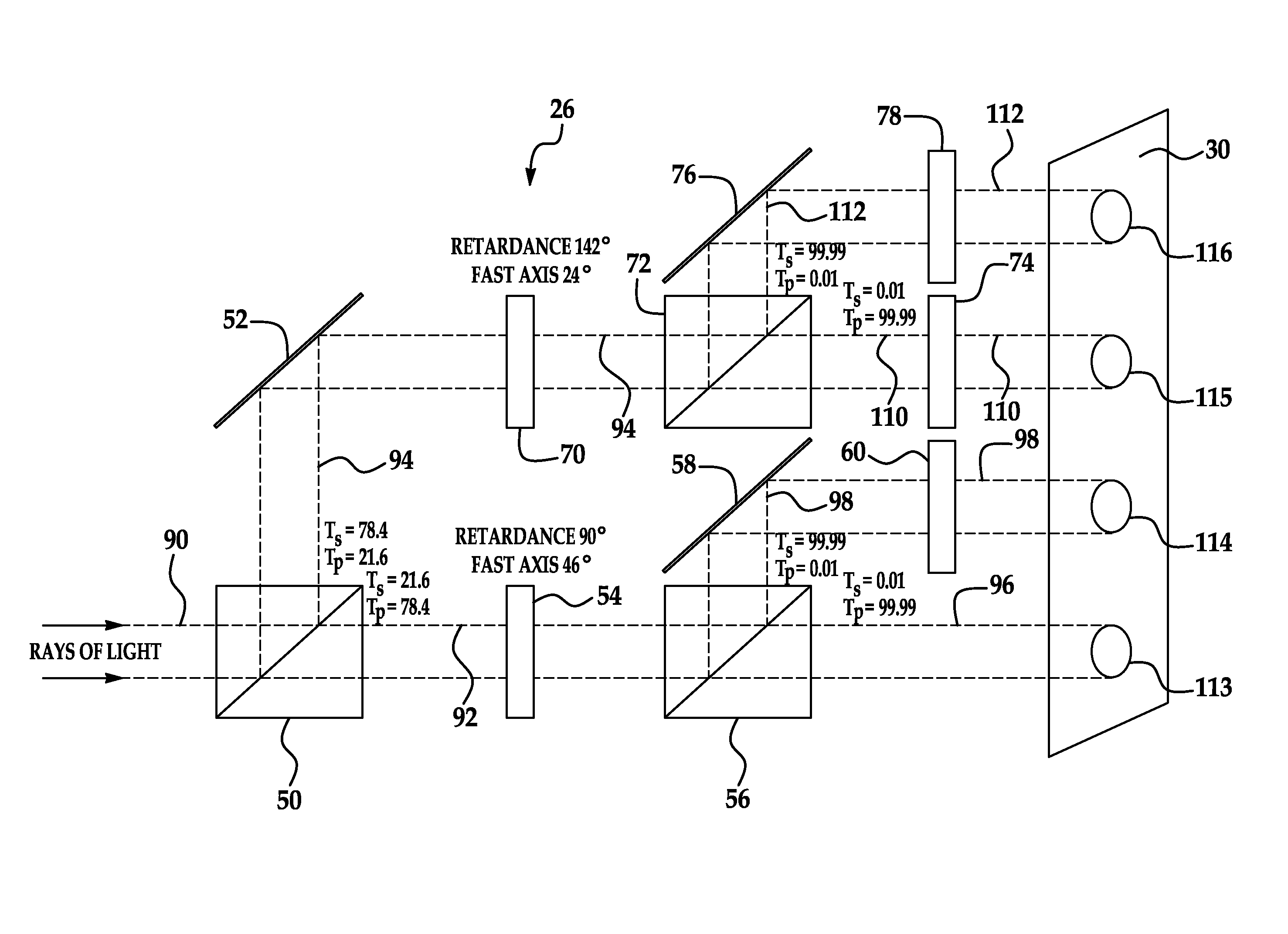
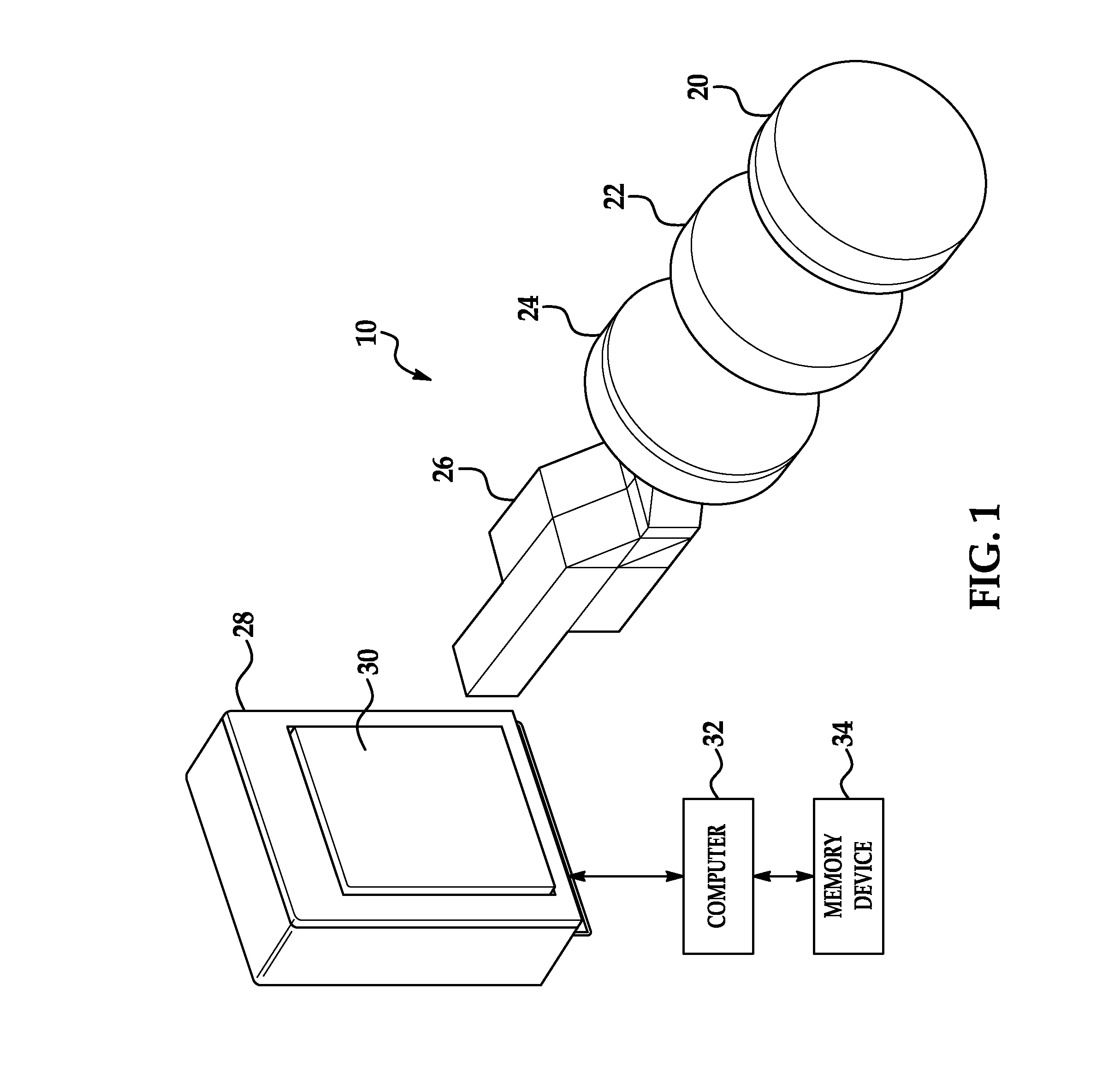
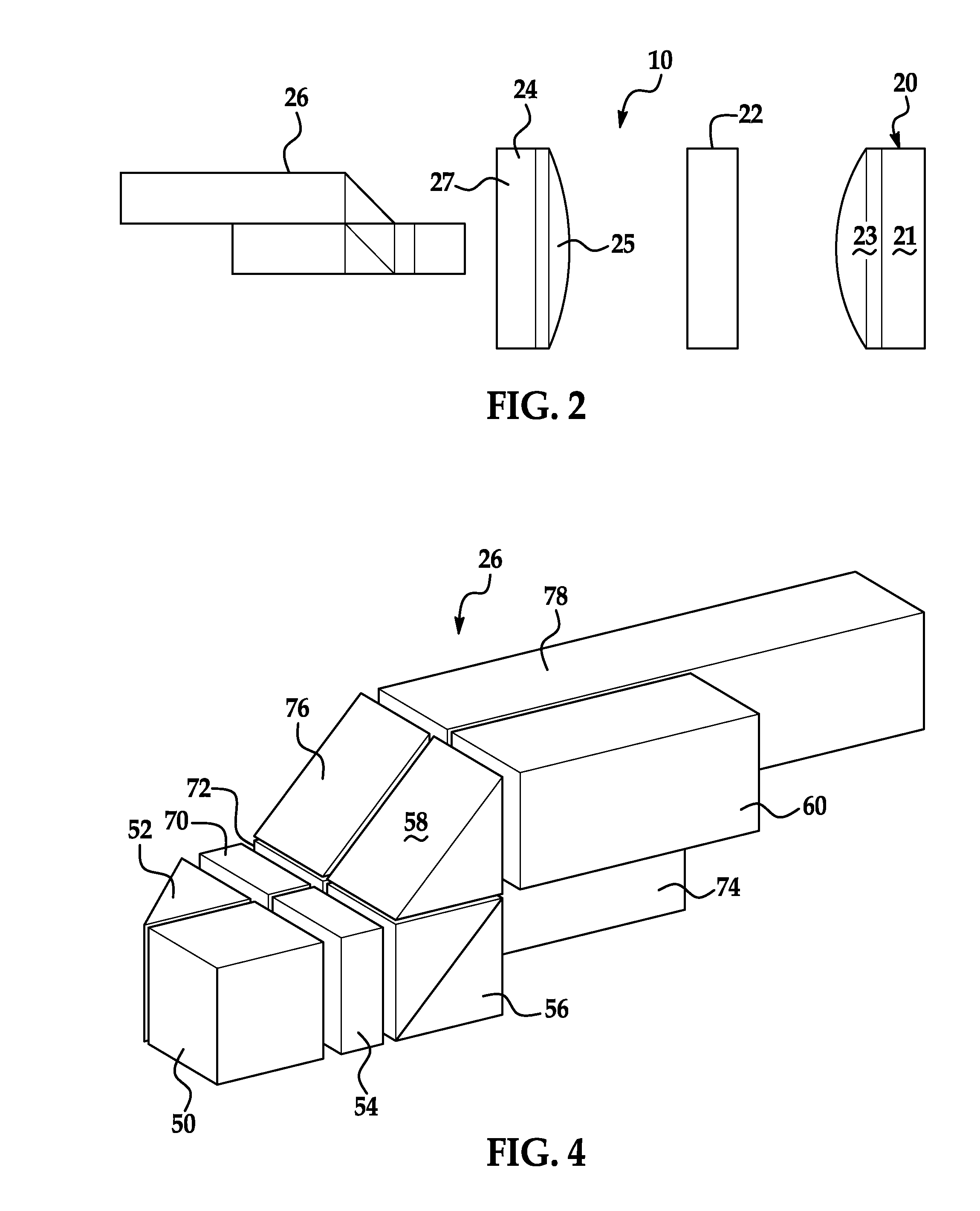
[0020]Referring now to FIGS. 1 and 2, an imaging polarimeter 10 in accordance with an exemplary embodiment is illustrated. The imaging polarimeter 10 includes a collimating lens 20, a bandpass spectral filter 22, a focusing lens 24, a monolithic beam splitter 26, a sensor array 28, a focal plane 30, a computer 32, and a memory device 34. The imaging polarimeter 10 of the invention determines Stokes parameters in real-time for received light. For purposes of this invention, the term real-time means 0.01 seconds or less. Further, the term sub-image means an image of an object formed by light rays traversing through a distinct optical path in a beam splitter on a focal plane. In one non-limiting embodiment, the imaging polarimeter 10 has a compact size less than or equal to 90 cubic inches. This allows the polarimeter 10 to be utilized in numerous applications requiring a compact package size.

[0021]The collimating lens 20 is provided to receive light rays from an object and to collimat...


PUM


Abstract

An imaging polarimeter and a method of utilizing the imaging polarimeter are provided. The method includes receiving a first light ray at a beam splitter and splitting the first light ray into second, third, fourth, and fifth light rays such that the second, third, fourth, and fifth light rays are simultaneously received on a flat focal plane. The method further includes outputting first, second, third, and fourth signals indicative of first, second, third, and fourth intensities, respectively, of the second, third, fourth, and fifth light rays, respectively, utilizing a sensor array disposed on the focal plane. The method further includes determining first, second, third, and fourth Stokes parameters for a pixel of the sensor array based on the first, second, third, and fourth signals, respectively, utilizing a computer.

Description

CROSS-REFERENCE TO RELATED APPLICATION[0001]This patent application claims priority to U.S. Provisional Patent Application Ser. No. 61 / 174,842, filed May 1, 2009, entitled “OPTIMAL SIMULTANEOUS STOKES' IMAGING POLARIMETER” and which is incorporated by reference herein in its entirety.BACKGROUND OF THE INVENTION[0002]Polarimeters have been developed that determine an angle of optical rotation of polarized light passing through a sample of material.[0003]Stokes parameters are a set of values that have been utilized to describe a polarization state of light. In particular, Stokes parameters describe light in terms of total intensity (I), a fractional degree of polarization (p) and shape parameters of a polarization ellipse. However, polarimeters have not utilized a rigid monolithic beam splitter therein that bends light rays onto one focal plane to determine Stokes parameters upon receipt of the light rays in real-time.[0004]Remotely collecting accurate polarimetric data (e.g., all fou...

Claims


Application Information

Patent Timeline
Patent Type & Authority Patents(United States)
IPC IPC(8): G01J4/00
CPCG01J4/04G01N21/21
Inventor MUDGE, JASON D.VIRGEN, MIGUEL
Owner LOCKHEED MARTIN CORP
Why Eureka
Try Eureka