Widely deployable charging system for vehicles

a charging system and vehicle technology, applied in charging stations, transportation and packaging, coupling device connections, etc., can solve the problems of unsuitable modern personal use vehicles, complex infrastructure modifications, and bulky intrusion of configurations,

Active Publication Date: 2012-11-13
GREEN DOT TRANSPORTATION INC
View PDF161 Cites 48 Cited by
  • Summary
  • Abstract
  • Description
  • Claims
  • Application Information

AI Technical Summary

Problems solved by technology

Apart from the fact that these systems do not offer automation, they do have safety issues arising from a potentially complex tangle of wires to be managed as well as possibilities of accidental drive off by a forgetful driver while the vehicle is still tethered to charging outlet.
Such systems suffer from the excessive inductive energy wastage and involve complex infrastructure modifications that are unsuitable for modern personal use vehicles.
Overhead pantographs: (RE29,994, U.S. Pat. No. 3,955,657, U.S. Pat. No. 5,651,434) All such systems are bulky intrusive configurations that need involved installation and maintenance of overhead bus bars.
Such systems still need a fair amount of manual alignment, but most importantly have very limited energy transfer rates for a safe level of radiation.
Conical / compliant receptacles: (U.S. Pat. No. 7,023,177, U.S. Pat. No. 6,614,204, U.S. Pat. No. 5,850,135, U.S. Pat. No. 5,696,367, U.S. Pat. No. 5,498,948, U.S. Pat. No. 5,272,431) These systems offer a limited tolerance to vehicle to parking stall misalignments.
In addition to expecting specific behavior from drivers, an accidental poor alignments as well as fast approach pose collision threat and will degraded the operation and reliability of such systems.
Such systems are relatively complex and depend on reliability of several sensors and motion control loops.
A miss-calibrated / drifted system could pose a spectrum of problems ranging from scratching the shiny paint of vehicle to simply not being able to connect the vehicle.
Apart from the intrusive nature of the robotic arms, both the trolleys as well as robotic systems are susceptible to vandalism in open infrastructure applications.
Such systems are either large footprint and tend to be bulky, or are imprecise (passive guidance) and need further connectivity assistance from conical, compliant or active search components.
Due to the one to one correspondence between the infrastructure side and vehicle side contactors, this arrangement necessitates the two cables as well as the two pantograph connectors be separated laterally by the worst case lateral misalignment specs of the vehicle plus the lateral dimension of the pantograph contactors, making it a bulky system, which is difficult to extend beyond two connectivity channels, a prime safety requirement from ground fault detection viewpoint.
This alignment in the U.S. Pat. No. 5,523,666 is made by active positioning of the infrastructure rails and suffers from the consequent disadvantages of an active positioning system.
Both U.S. Pat. No. 5,252,078 and U.S. Pat. No. 5,523,666 suffer from the disadvantages of a system requiring precise alignment—whether passive or active, as well as carry potential for damage and reduced reliability and safety due to drivers accidentally driving into the system.
Consequently suffers from either precise positioning or too large contactor spacing and size.
As described, this system is also bulky and needs involved installation.
Additionally, U.S. Pat. No. 4,850,879 can be damaged due to accidental driving in.

Method used


Image

  • Widely deployable charging system for vehicles
  • Widely deployable charging system for vehicles
  • Widely deployable charging system for vehicles

Examples


Embodiment Construction

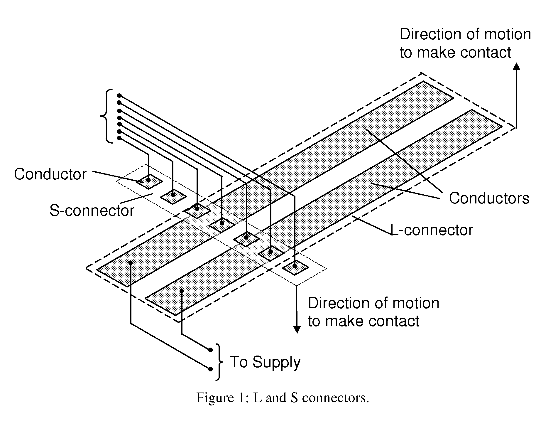
[0033]A mechanical, electrical and telecommunication arrangement to transfer electrical energy to a vehicle is described in this invention. At the core of the system (see FIG. 1) is a pair of linear arrays of conductive elements insulated from each other. A specific rendition where one of the arrays is a 1×7 array (labeled as S-Connector) and the other is a 2×1 labeled L connector is shown in the FIG. 1. One of the connectors (either S or L connector) is placed on the infrastructure side and the other on a vehicle. When the array on the vehicle is in the proximity of the array on the ground, such that the two have an overlap, one or both of the arrays are moved towards each other. This causes the array elements—labeled as “conductors”, to mate and form an electrical contact in the overlap region. Depending on the relative position of the vehicle in the parking stall, an arbitrary group of conductors from S connector may come in contact with an equally arbitrary group of conductors f...


PUM


Abstract

A mechanical, electrical and telecommunication system to electrically connect a vehicle to an electricity source to transfer energy to the vehicle is presented. In one rendition the system has a stationary portion on the road or infrastructure side, and a moving member on the vehicle. The system is designed to tolerate misalignments of a parked vehicle with respect to the parking stall. The infrastructure or road side component of the system being mechanically static is designed rugged and therefore is widely deployable. The system along with moving member is fail-safe and poses no threat to humans, the vehicle being charged or the vehicles sharing the road. An important component of the system is a pair of rigid, insulating strips with a series of conductors on each of them, placed at approximately right angles to each other. One of the strips is mounted on the infrastructure or road side and the other on the vehicle. The two strips cover the lateral and longitudinal misalignment of the parked vehicle. As long as the two strips have an overlap, the connection can be made by the conductors in the overlap region. The system is designed to operate only in the active presence and active desire of a vehicle to connect to the infrastructure or road side stationary part.

Description

CROSS-REFERENCE TO RELATED APPLICATIONS[0001]This application claims priority over U.S. Provisional Patent Application 60 / 947,954, filed Jul. 4, 2007, titled “Widely deployable charging system for vehicles”, which is incorporated herein by reference in its entirety.DESCRIPTION OF DRAWINGS[0002]FIG. 1: L and S connectors.[0003]FIG. 2: Electrical connections and geometry definition.[0004]FIG. 3: Splitting the L-connector conductors.[0005]FIG. 4: Front underside mounting.[0006]FIG. 5: Underside mounting.[0007]FIG. 6: Actuating Mechanism.[0008]FIG. 7: Mechanical system: Configuration 1.[0009]FIG. 8: Mechanical system: Configuration 2.[0010]FIG. 9: Equal force distributor replacement mechanism for link 10.[0011]FIG. 10: Alignment preserving replacement mechanism for link 10[0012]FIG. 11: Electrical connections, interlock and geometry definition[0013]FIG. 12: Steps to select contacting conductors, executing on microprocessor A.[0014]FIG. 13 Steps to select contacting conductors, executing...

Claims


Application Information

Patent Timeline
Patent Type & Authority Patents(United States)
IPC IPC(8): B60L1/00H02J7/00
CPCH01R13/629H01R13/70B60L11/1816B60L5/00B60L11/1827H01R2201/26Y02T90/14Y02T10/7005Y02T90/125Y02T90/121B60L53/14B60L53/35Y02T10/70Y02T10/7072Y02T90/12
Inventor PATWARDHAN, SATYAJIT
Owner GREEN DOT TRANSPORTATION INC
Why Eureka
Try Eureka