Method and apparatus for broadband electromagnetic modeling of three-dimensional interconnects embedded in multilayered substrates

a technology of three-dimensional interconnections and multi-layer substrates, applied in the field of methods and equipment, can solve the problems of limited analysis of the effects of each circuit layer, inadequate conventional modeling of the layers, etc., and achieve the effect of improving computational efficiency

Inactive Publication Date: 2012-11-13
CADENCE DESIGN SYST INC
View PDF6 Cites 86 Cited by
  • Summary
  • Abstract
  • Description
  • Claims
  • Application Information

AI Technical Summary

Benefits of technology

[0015]According to another aspect, two or more of the sub-grids may lie in substantially parallel planes with uniformly spaced grid points. Depending on the operational setting, these sub-grids may lie in parallel planes or planes that are approximately parallel (e.g., within some engineering tolerance such as 10%). Uniform spacing of all grid points or a substantial portion of the grid points within a sub-grid enables improved computational efficiency for related spectral computations (e.g., as in the FFT (Fast Fourier Transform)).
[0021]According to another aspect, the grid may include a plurality of sub-grids that lie in substantially parallel planes with uniformly spaced grid points. Depending on the operational setting, these sub-grids may lie in parallel planes or planes that are approximately parallel (e.g., within some engineering tolerance such as 10%). Uniform spacing of all grid points or a substantial portion of the grid points within a sub-grid enables improved computational efficiency for related spectral computations (e.g., as in the FFT (Fast Fourier Transform)).

Problems solved by technology

According to some conventional approaches, analysis of these effects on each circuit layer has been limited to evaluating such effect due to current flowing only in the layer itself.
As a result, conventional modeling of the layers has become inadequate and more accurate three-dimensional modeling of the electromagnetic effects will be needed for future applications.

Method used


Image

  • Method and apparatus for broadband electromagnetic modeling of three-dimensional interconnects embedded in multilayered substrates
  • Method and apparatus for broadband electromagnetic modeling of three-dimensional interconnects embedded in multilayered substrates
  • Method and apparatus for broadband electromagnetic modeling of three-dimensional interconnects embedded in multilayered substrates

Examples


Embodiment Construction

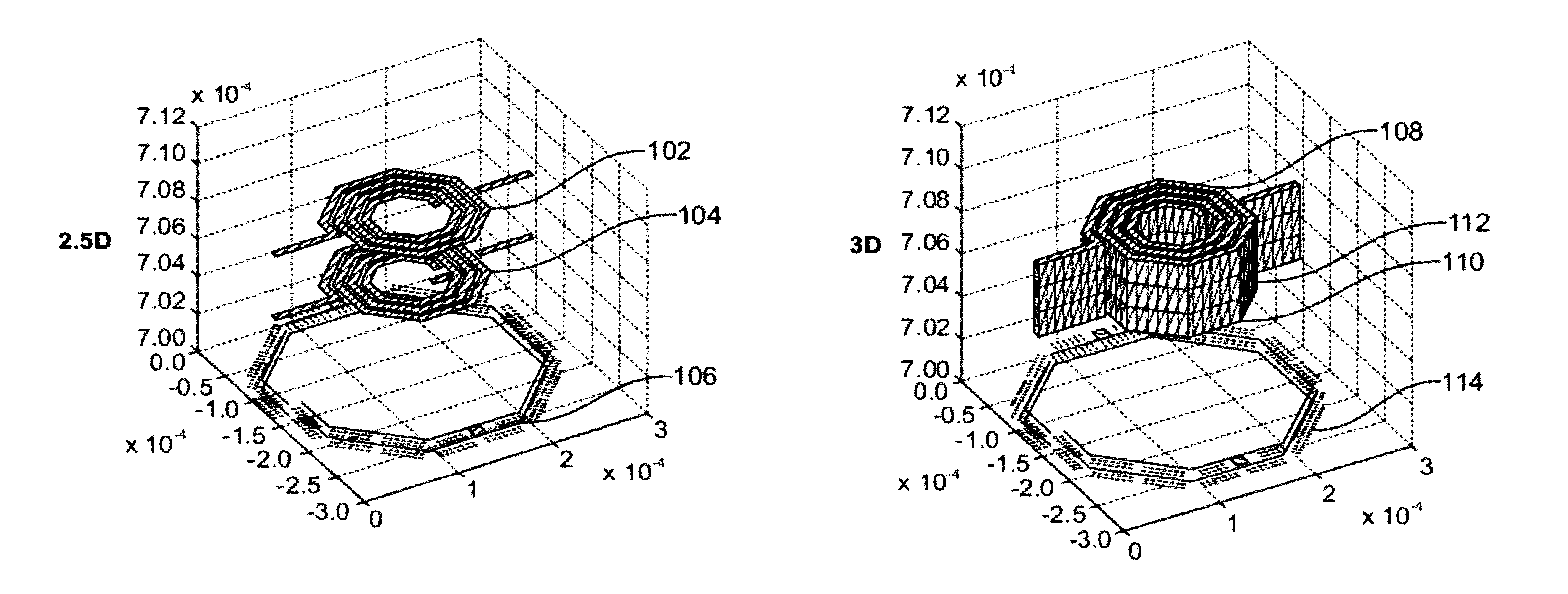
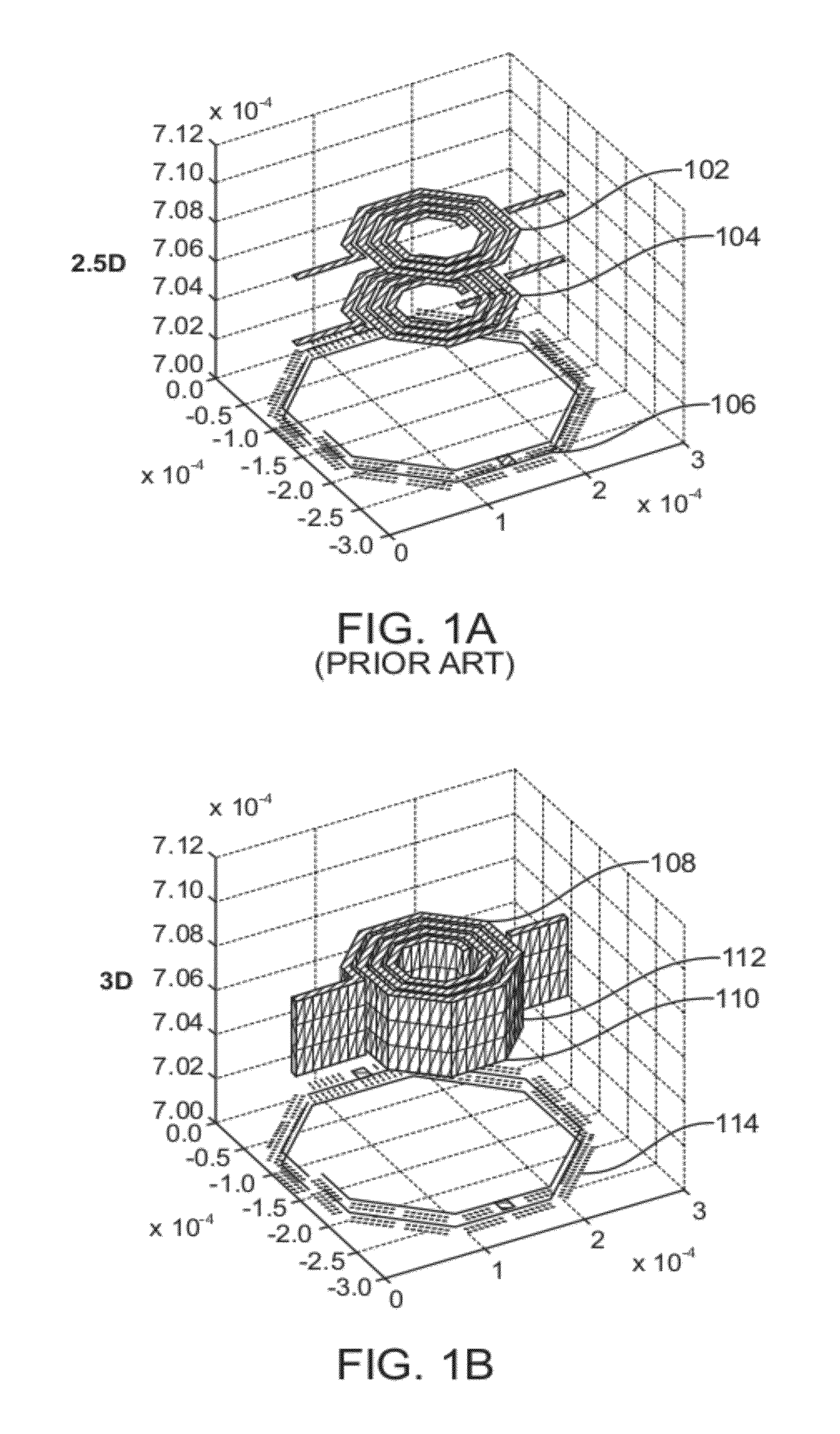
[0046]FIG. 1A shows a conventional “2.5D model” (i.e., 2.5 dimensional) of a spiral inductor with a mesh model for a top wall 102 and a bottom wall 104. A lower layer 106 on the substrate is also shown. The 2.5D model supports current flow in the x-direction and y-direction only while implicitly introducing z-directed currents (i.e., normal to the substrate) in association with the via currents. See, for example, “Method and apparatus for determining interactive electromagnetic effects among conductors of a multi-layer circuit”, U.S. Pat. No. 7,127,688, issued Oct. 24, 2006, which is incorporated by reference in its entirety. See also “Large-scale Broadband Parasitic Extraction for Fast Layout Verification of 3-D RF and Mixed-Signals On-chip Structures”, F. Ling et al., IEEE Transactions on Microwave Theory and Techniques, Vol. 53, No. 1, January 2005.

[0047]In general, the 2.5D model has provided sufficient accuracy in when the layout conductors are predominantly thin. In today's 90...


PUM


Abstract

Systems and methods for modeling a multilayer integrated circuit include three-dimensional interconnect models in multilayered substrates for greater accuracy. Mesh models are used to resolve effects of nearby elements and grid models are used to resolve effects of far-away elements. Sidewall mesh elements of three-dimensional interconnects are projected onto parallel (or substantially parallel) grids between the top and bottom walls of the interconnects so that grid models can be used to resolve three-dimensional effects of interconnects in multilayered substrates.

Description

CROSS REFERENCE TO RELATED APPLICATIONS[0001]This application claims the benefit of U.S. Provisional Application No. 61 / 120,648, filed Dec. 8, 2008, and incorporated herein by reference in its entirety.BACKGROUND OF THE INVENTION[0002]1. Field of the Invention[0003]The present invention relates to the design of multi-layer circuits, e.g., integrated circuits or printed circuits, and, more particularly, to determining the electromagnetic effects on the performance of a multi-layer circuit with three-dimensional interconnects from a bias applied to the circuit.[0004]2. Description of Related Art[0005]As the size of electrical devices and interconnecting conductors of multi-layer circuits, especially multi-layer integrated circuits, continues to decrease and the bandwidth of operation continues to increase, the effects on the performance of the circuit due to electromagnetic effects in the various layers of the circuit have become more pronounced.[0006]According to some conventional ap...

Claims


Application Information

Patent Timeline
Patent Type & Authority Patents(United States)
IPC IPC(8): G06F9/455G06F17/50
CPCG06F17/5018G06F17/5036G06F17/5068G06F30/367G06F30/39G06F30/23G06F30/394
Inventor OKHMATOVSKI, VLADIMIRYUAN, MENGTAOPHELPS, RODNEY
Owner CADENCE DESIGN SYST INC
Why Eureka
Try Eureka