Automated lifecycle management of a computer implemented service

a lifecycle management and computer technology, applied in the field of automated lifecycle management of computer implemented services, can solve the problems of difficult management of physical it (information technology) infrastructure, difficult manual changes, high cost, etc., and achieve the effect of facilitating more automation of service development, reducing development costs, and being easy to manag

Active Publication Date: 2012-11-13
HEWLETT-PACKARD ENTERPRISE DEV LP
View PDF64 Cites 53 Cited by
  • Summary
  • Abstract
  • Description
  • Claims
  • Application Information

AI Technical Summary

Benefits of technology

[0012]An object is to provide improved apparatus or methods. In one aspect the invention provides a system for automated lifecycle management of a computer implemented service, according to requirements, the system having a service model arranged to represent at least part of the service at a given development state in the lifecycle, and a transition model representing allowed operations to change the service model to a different one of the development states of the service, according to the requirements, and the transition model having a transparent structure suitable for automated inspection of the allowed operations, and suitable for automated adaptation of the allowed operations. A service model state manager is arranged to cause the service model to be developed to another of its states of development according to the transition model. This can help facilitate more automation of the service development than for example code in a closed and fixed form such as for example a compiled program for altering the service model, the code not being open to inspection and adaptation without expert human input. This in turn can enable more complex services to be developed, or reduce development costs for example. Also it can be easier to manage, in the sense of enabling more reuse of code, more human readability, and enable easier automated checks for inconsistencies, automated correction and adaptation to changes in service requirements for example.

Problems solved by technology

Physical IT (information technology) infrastructures are difficult to manage.
Changing the network configuration, adding a new machine or storage device are typically difficult manual tasks.
This makes such changes expensive and error prone.
It also means that the change can take several hours or days to take place, limiting the rate at which reconfiguration can take place to take account of changing business demands.
Sometimes the reconfiguration can take months, as more equipment needs to be ordered before it can be implemented.
For example, an infrastructure designed for running desktop office applications during the day may not be suitable for running complicated numerical analysis applications during the night.
In a single physical IT infrastructure, separate tasks can interfere with each other.
One problem is how to isolate the network traffic, the data storage and processing of these computations from other tasks using the same infrastructure.
Without isolation undesirable interference between the tasks is likely to occur rendering such sharing an unacceptable risk.
This requires specialized hardware which makes it expensive.
In addition in the UDC a physical machine can only ever be in a single physical infrastructure.
This means that all programs running on that physical machine will be exposed to the same networking and storage environment: they can interfere with each other and the configuration may not be optimal for all programs.
In UDC although a physical machine can be reassigned to different infrastructure instances, called farms, at different times, it can only be assigned to one farm, at any given moment: it is not possible to share a physical machine between farms.
This limits the utilization that levels that can be achieved for the hardware, requiring the customer to purchase more hardware than is necessary.
Multi-tenancy systems can reduce maintenance and management challenges for providers, but it can be more difficult to ensure customer specific service levels.
Isolated-tenancy systems provide for greatest performance flexibility and greatest security, but present greater maintenance challenges.
Rendering service instances into shared virtualized resource pools presents configuration, deployment and management challenges, and various approaches are known.
Services do not conform to a one size fits all approach.
The prototype they describe is only able to deal with network topology matching and management.

Method used


Image

  • Automated lifecycle management of a computer implemented service
  • Automated lifecycle management of a computer implemented service
  • Automated lifecycle management of a computer implemented service

Examples


Embodiment Construction

Definitions:

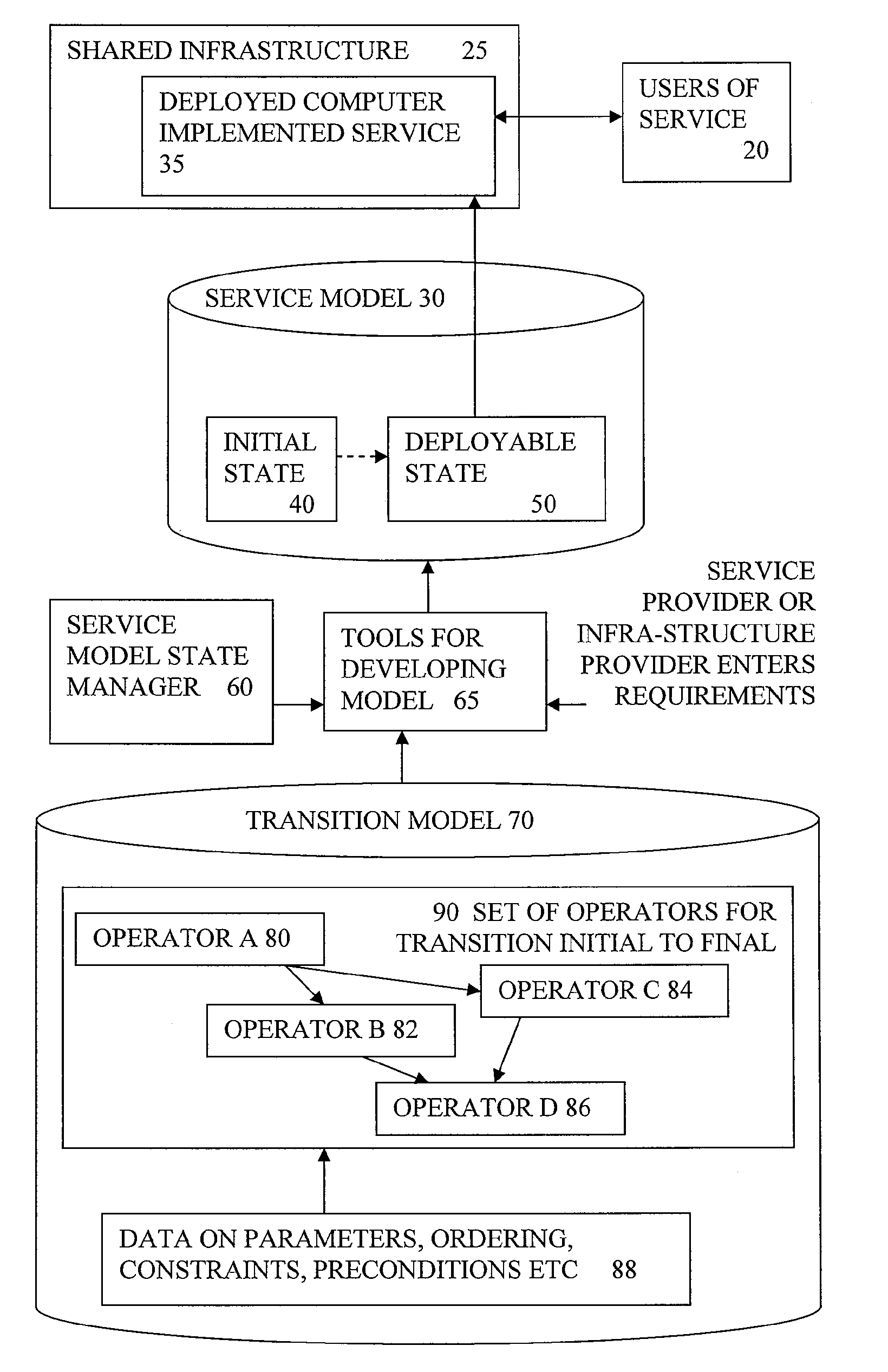
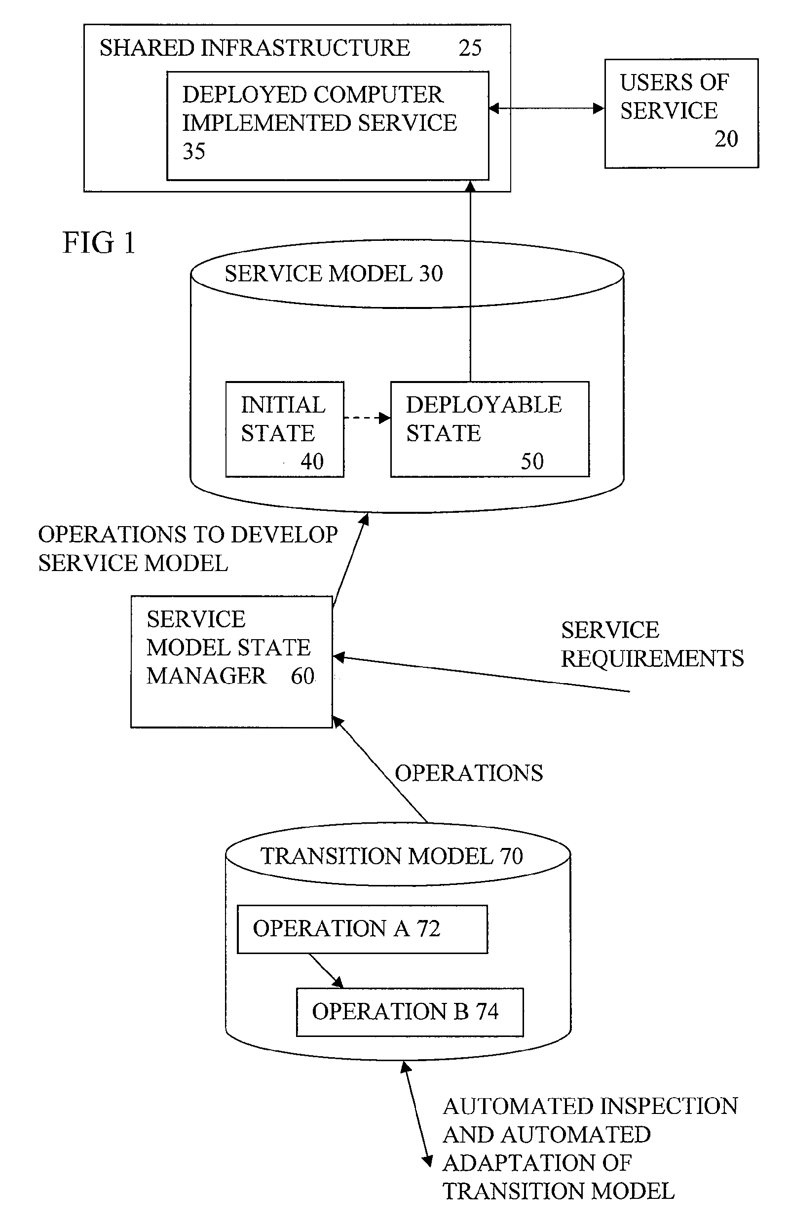
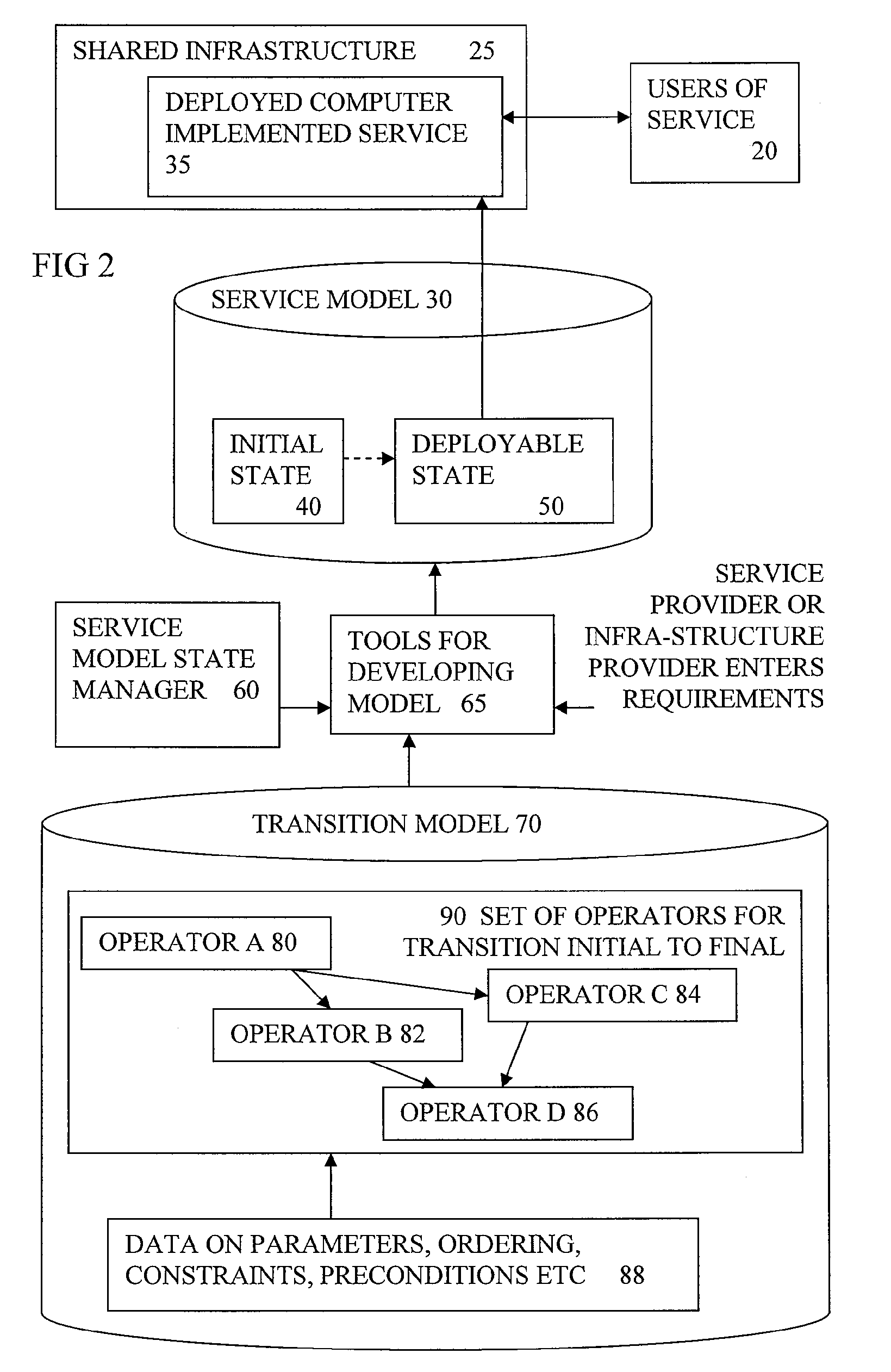
[0031]“lifecycle” is defined as encompassing some or all stages of development of a service such as requirements collection, design, deployment, testing and run time management. Deployment is the process of instantiating and reifying a design of a service so that it can be made available to users.[0032]“lifecycle management” can encompass management of part or all of the lifecycle.[0033]“user” of a service can encompass a human user or another service.[0034]“requirements” can include functional and non-functional requirements for a given service, and can alter during the lifecycle.[0035]“model” is intended to encompass any kind of representation of a design and can encompass data structures, or code or combinations of these, for example, and can be made up of sub models located at different locations for example.[0036]“state manager” is intended to encompass any kind of software, service, tool or process or combination of these, for managing the transition to another sta...


PUM


Abstract

A system for automated lifecycle management of a computer implemented service, according to requirements, having a service model (30) representing the service at a given development state in the lifecycle, and a transition model (70) representing allowed operations to change the service model to a different one of the development states of the service, according to the requirements, and the transition model having a transparent structure suitable for automated inspection of the allowed operations, and suitable for automated adaptation of the allowed operations. The service model can be developed to another of its states of development according to the transition model. This can help facilitate more automation of the service development than for example code in a closed and fixed form such as for example a compiled program for altering the service model. This in turn can enable more complex services to be developed, or reduce development costs.

Description

RELATED APPLICATIONS[0001]This application relates to the following applications: Ser. No. 12 / 261,346 filed on Oct. 30, 2008, titled “CHANGE MANAGEMENT OF MODEL OF SERVICE”, (applicant reference number 200801919), and titled “AUTOMATED OPTIMISATION OF MODEL OF SERVICE”; Ser. No. 12 / 808,223 filed on Jun. 15. 2010, titled “INCORPORATING DEVELOPMENT TOOLS IN SYSTEM FOR DEPLOYING COMPUTER BASED PROCESS ON SHARED INFRASTRUCTURE”; Ser. No. 12 / 808,229 filed on Jun. 15, 2010, titled “MODEL BASED DEPLOYMENT OF COMPUTER BASED BUSINESS PROCESS ON DEDICATED HARDWARE”; PCT / US2007 / 088334 filed on Dec. 20, 2010, titled “VISUAL INTERFACE FOR SYSTEM FOR DEPLOYING COMPUTER BASED PROCESS ON SHARED INFRASTRUCTURE”; Ser. No. 12 / 808,231 filed on Jun. 15, 2010, titled “MODELLING COMPUTER BASED BUSINESS PROCESS FOR CUSTOMISATION AND DELIVERY”; Ser. No. 12 / 808,233 filed on Jun. 15, 2010, titled “MODELLING COMPUTER BASED BUSINESS PROCESS AND SIMULATING OPERATION”; Ser. No. 12 / 808,227 filed on Jun. 15. 2010, ...

Claims


Application Information

Patent Timeline
Patent Type & Authority Patents(United States)
IPC IPC(8): G06F9/44
CPCG06F8/10G06F8/70
Inventor WILCOCK, LAWRENCEEDWARDS, NIGELBELROSE, GUILLAUME ALEXANDREROLIA, JEROMEKIRSCHNICK, JOHANNES
Owner HEWLETT-PACKARD ENTERPRISE DEV LP
Why Eureka
Try Eureka