Guide device for a motorized table comprising a unit that groups the table controls together

a technology of motorized tables and guide devices, which is applied in the direction of electric propulsion mounting, wheelchairs/patient conveyances, transportation and packaging, etc., can solve the problems of increasing the risk of injury, reducing the safety of medical staff, and reducing the safety of patients, so as to facilitate the handling of the control device and the patient's transfer, and avoid any risk of being forgotten

Inactive Publication Date: 2012-11-20
STERIS SURGICAL TECH
View PDF10 Cites 20 Cited by
  • Summary
  • Abstract
  • Description
  • Claims
  • Application Information

AI Technical Summary

Benefits of technology

[0012]The present invention more particularly aims at remedying the drawbacks of the systems previously described by providing a control unit grouping the means controlling the motion of the table and the means controlling the positioning of the top of the table, so that the operating table is controlled by only one control system. For this purpose and according to a first aspect, the invention relates to a guiding device of a motor driven operating table comprising a top intended to support a patient and a base supporting said top, said base comprising a motor unit, of the type including a control unit intended to control the motion of the table, said control unit being coupled to the motor unit of the table, and characterised in that the control unit comprises a housing including a recess so arranged as to receive a control device intended to control the positioning of the top with respect to the base supporting the top.

Problems solved by technology

Such patient's transfers remain relatively not easy and entail for the medical staff injury hazards, and for the patient, a risk of worsening of injuries.
Although the patient's transfer onto the operating table is no longer carried out with a direct handling of the patient, the system described however requires some physical strength to be able to move the top from one support to another.
Besides, the system reveals to be difficult to handle.
Such a system further has the drawback relating to the control unit arranged in the form of a separate unit.
This reveals to be a problem during the patient's transfer, since no storage space is provided on the operating table for said control unit.
In addition, due to the construction thereof, said control unit is cumbersome and little ergonomic.
A first drawback of such a handlebar is related to the fact that the device controlling the position of the top, which is separated from the control unit, is a unit independent of the operating table.
Now, as there is no specific and protected location on the table, these are often forgotten on the rails, or damaged or deteriorated against the beds during the patients' transfer operations.
A second drawback is connected with the dissociated and distant position of the remote control device from the handlebar controlling the motion of the table.
In order to avoid the successive switching from one device to another, certain users prefer to hold the remote control device in their hands all along the transfer, which makes the guiding of the table rather difficult.
Another drawback is connected to the unidirectional control transfers, from the control unit to the motor, without any feedback of information.
The user of the operating table has no way to know immediately the causes of the non-execution of the motion and possibly to remedy it.
Another drawback lies in the utilisation of wireless connections.
Such connections can be interfered with and thus they are not reliable.
Now, a bad communication between the control and the wheel generates speed variations, stops or even untimely failures.
In addition, because of the low reliability of the infrared connection and of the absence of feedback from the motor, it seems difficult to increase the number of controls of the table from the handlebar.
Eventually, a last drawback is connected to the fact that the control handlebar is self-contained.
Besides, it may happen that the controls are unloaded during the motion of the tables, which thus blocks them with the patients during the transfer thereof.

Method used


Image

  • Guide device for a motorized table comprising a unit that groups the table controls together
  • Guide device for a motorized table comprising a unit that groups the table controls together
  • Guide device for a motorized table comprising a unit that groups the table controls together

Examples


Embodiment Construction

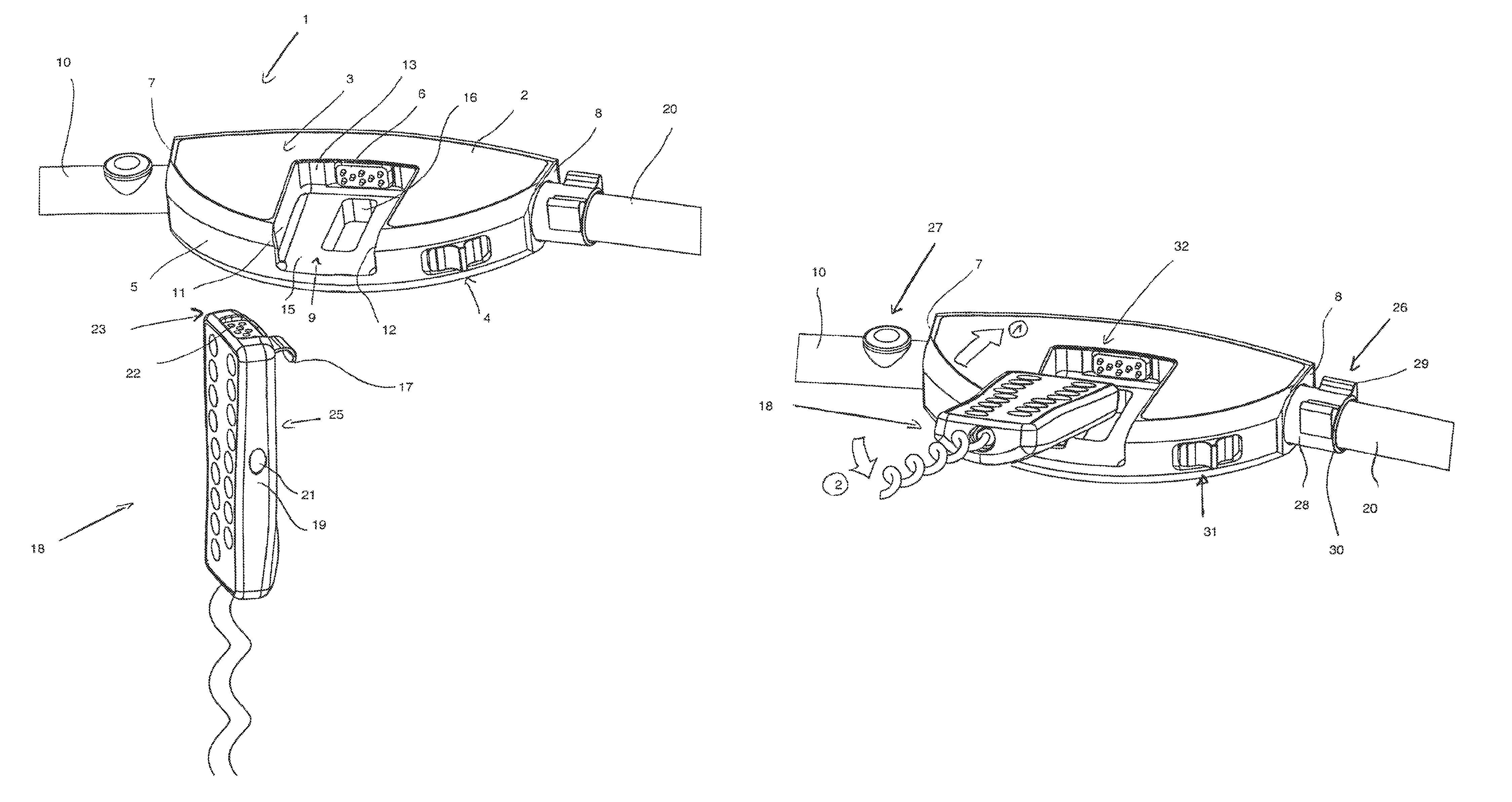
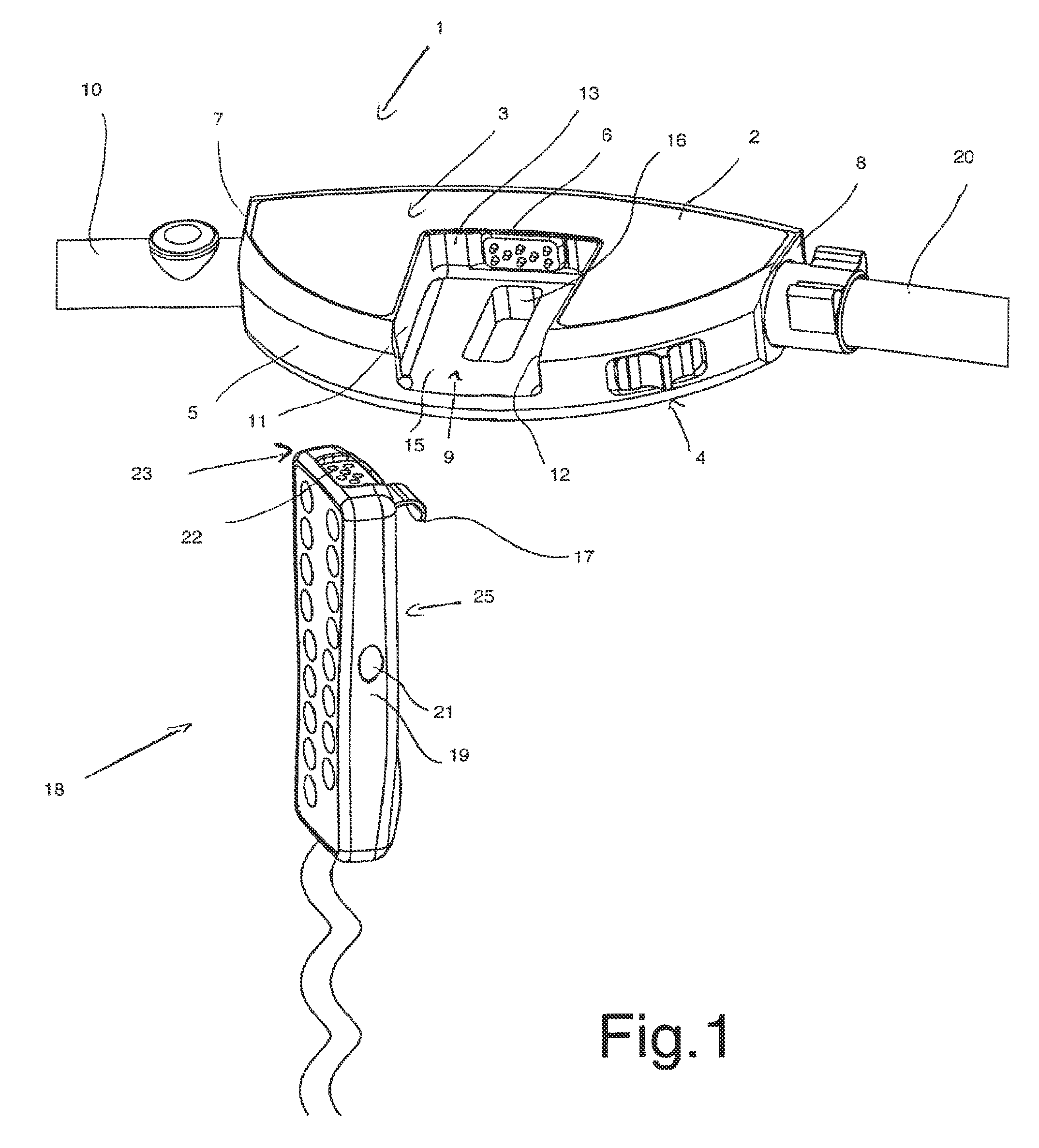
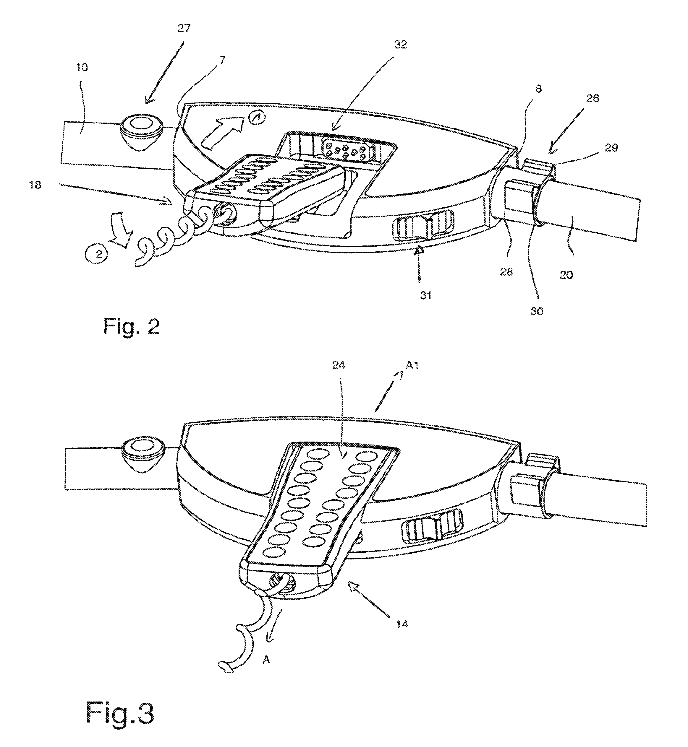
[0023]As regards FIGS. 1 to 4, a device for guiding a motor driven operating table, more particularly intended to surgical operations, is described. According to a particular configuration, the operating table comprises a top for supporting a patient, said top being mounted on a supporting base. The base includes a motor, making it possible to actuate the motion of the table as well as a wheel associated with said motor. This will be called a motor driven wheel in the following. As regards the top, it is generally formed by a juxtaposition of three parts intended to receive the patient's head, back and hips, as well as his / her legs, respectively. Advantageously, the end parts (parts forming the headstall and the leg holders) are rotatingly mounted with respect to the central part of the top.

[0024]The operating table further includes rails fixed on the side edges of the top by means of cross pieces. More particularly, each part composing the top includes, on the respective side edges...


PUM


Abstract

The invention relates to a guide device for a motorized operating table comprising a bed intended to support a patent and a base supporting said bed, said base comprising a motor unit, of the type comprising a control unit intended to control the movement of the table, said control unit being coupled to the table motor unit, and characterized in that the control unit comprises a casing comprising housing designed to accommodate a control device intended to control the position of the bed with respect to the base supporting the bed and with respect to the movement of the motorized table.

Description

CROSS-REFERENCE TO RELATED APPLICATIONS[0001]This application is a National Phase Entity of International Application No. PCT / FR2007 / 000599, filed Apr. 10, 2007, claiming priority to French Patent Application No. FR 06 / 03176, filed Apr. 10, 2006, both of which are incorporated by reference herein.BACKGROUND AND SUMMARY[0002]The invention relates to the field of motor driven operating tables, intended more particularly to surgical operations.[0003]During surgical operations, patients have to be transferred from one place to another and more particularly from the induction room to the operation room, where they are to undergo the surgical operation, then from the operation room to the recovery room. The transfer of the patients is conventionally performed using transport trolleys which are manually pushed by the medical staff. They are transferred from their beds to the transport trolley to be brought to the operating room, where they are transferred from the transport trolley to the ...

Claims


Application Information

Patent Timeline
Patent Type & Authority Patents(United States)
IPC IPC(8): A47B71/00A61G5/04
CPCA61G13/02
Inventor L'HEGARAT, JEAN-MARIECOLLOT, OLIVIERFRANCO, FILIPE
Owner STERIS SURGICAL TECH
Why Eureka
Try Eureka