Foil container

a technology of oil containers and oil, applied in the field of oil containers, can solve the problems of cost-intensive manufacturing and achieve the effect of preventing the reaction of two components with each other

Inactive Publication Date: 2012-11-20
HILTI AG
View PDF12 Cites 77 Cited by
  • Summary
  • Abstract
  • Description
  • Claims
  • Application Information

AI Technical Summary

Benefits of technology

[0011]Advantageously, the second foil bag has at least two foil bag chambers for separately storing the at least two components of the multi-component mass. Thereby, a reaction of the two components with each other is prevented. In order to form a separate foil bag chambers in the second foil bag, advantageously, a separation wall is provided in the second foil bag. The separation wall prevents a direct contact of the at least two components with each other during storage of the components in the second foil bag. Thus, there is no contact region between the two components in which a reaction can take place.
[0012]If a multi-component mass consists of only two component, then, the first foil bag stores a first portion of the first component of the multi-component mass, and the at least two foil bag chambers of the second foil bag store, respectively, a second portion of the first component and the second component of the multi-component mass different from the first component. The larger of the two components of the two-component mass can be divided in two equal or unequal portions. This makes possible to obtain different mixing ratios of two components with a constant dimension of the foil container. E.g., it is possible to realize in a conventional foil container dimensioned for a mixture ratio 3:1 and a differing therefrom, mixture ratio 5:1.
[0014]By dividing the first component in two portions stored in separate foil bags, the peroxide content can be concentrated in one of the chambers of the second foil bag of the foil container with peroxide content amounting to above 1%. Thereby, the peroxide content with regard to the components in the second foil bag which has two foil bag chambers can be reduced to below 1% at mixture ratios from 1:1 to 10:1. Thus, this embodiment of the invention permits to realize a strong injection mortar that can be free of any marking and, thus, be handled without any particular procedure.
[0017]Advantageously, at least one of the first and second foil bags has, at its end adjacent to the receiving section of the head portion, a weakness that opens under pressure. Thereby, upon application of pressure, e.g., with a pressing piston of the ejection device, the foil of the foil bag is teared off in the region of the weakness. This foil bag can be open very easily. The weakness of the foil bag is preferably formed with a laser which removes a portion of the layers of a usually multi-layer foil of the foil bag. If the multi-layer foil has an isolation layer, then, advantageously the outer layer or layers are removed at least in one region up to the isolation layer.

Problems solved by technology

A drawback of foil containers, such as disclosed, e.g., in EP 0 914 069 B1, consists in that they can be used only for storing two-component masses and can be inserted only in one receptacle of an ejection device.
When the use of three-component masses or masses with more than three components is required, up to now, special ejection devices and containers, which have a complicated construction and which are, therefore, cost-intensive in manufacturing, were required.

Method used


Image

  • Foil container
  • Foil container
  • Foil container

Examples


Embodiment Construction

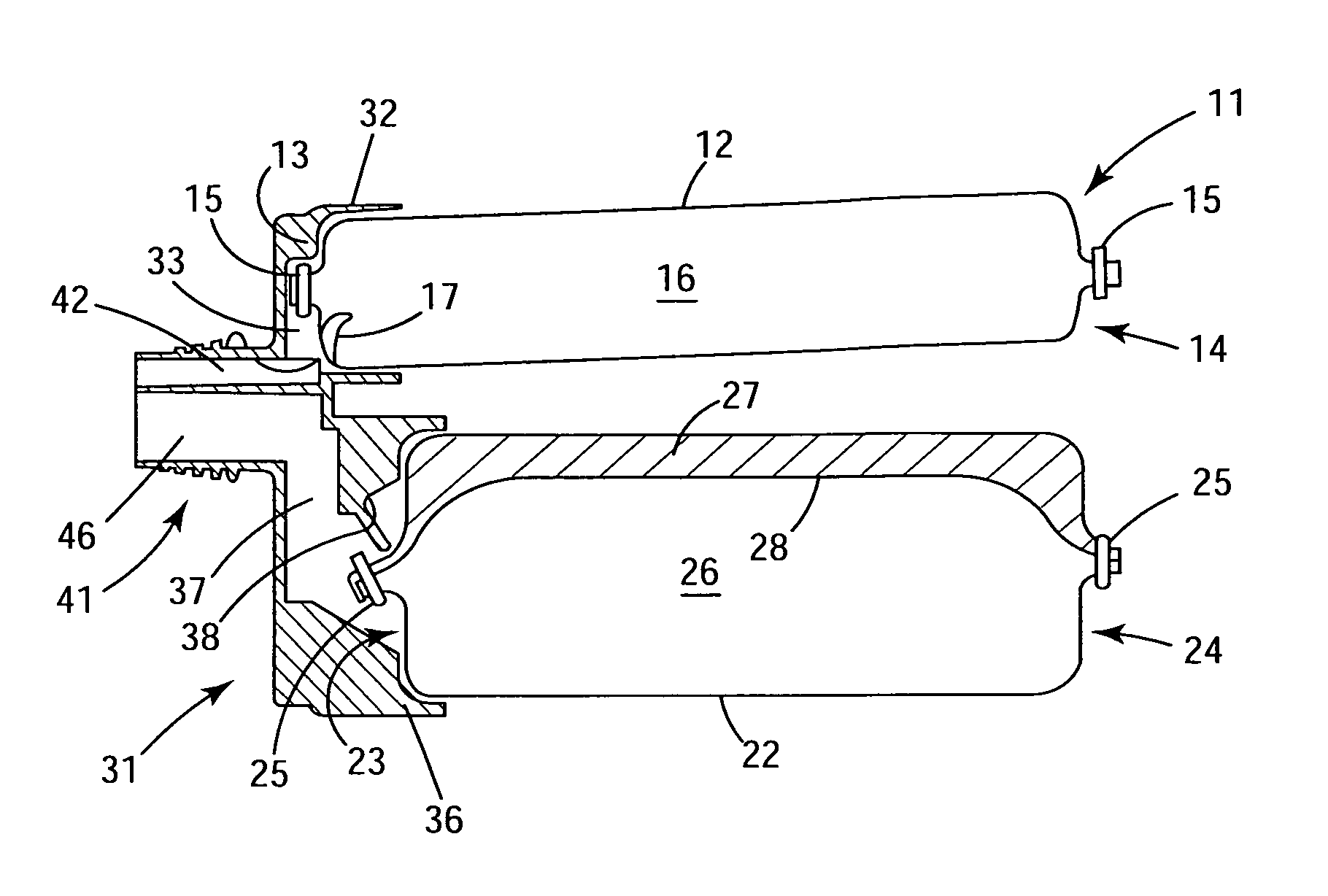
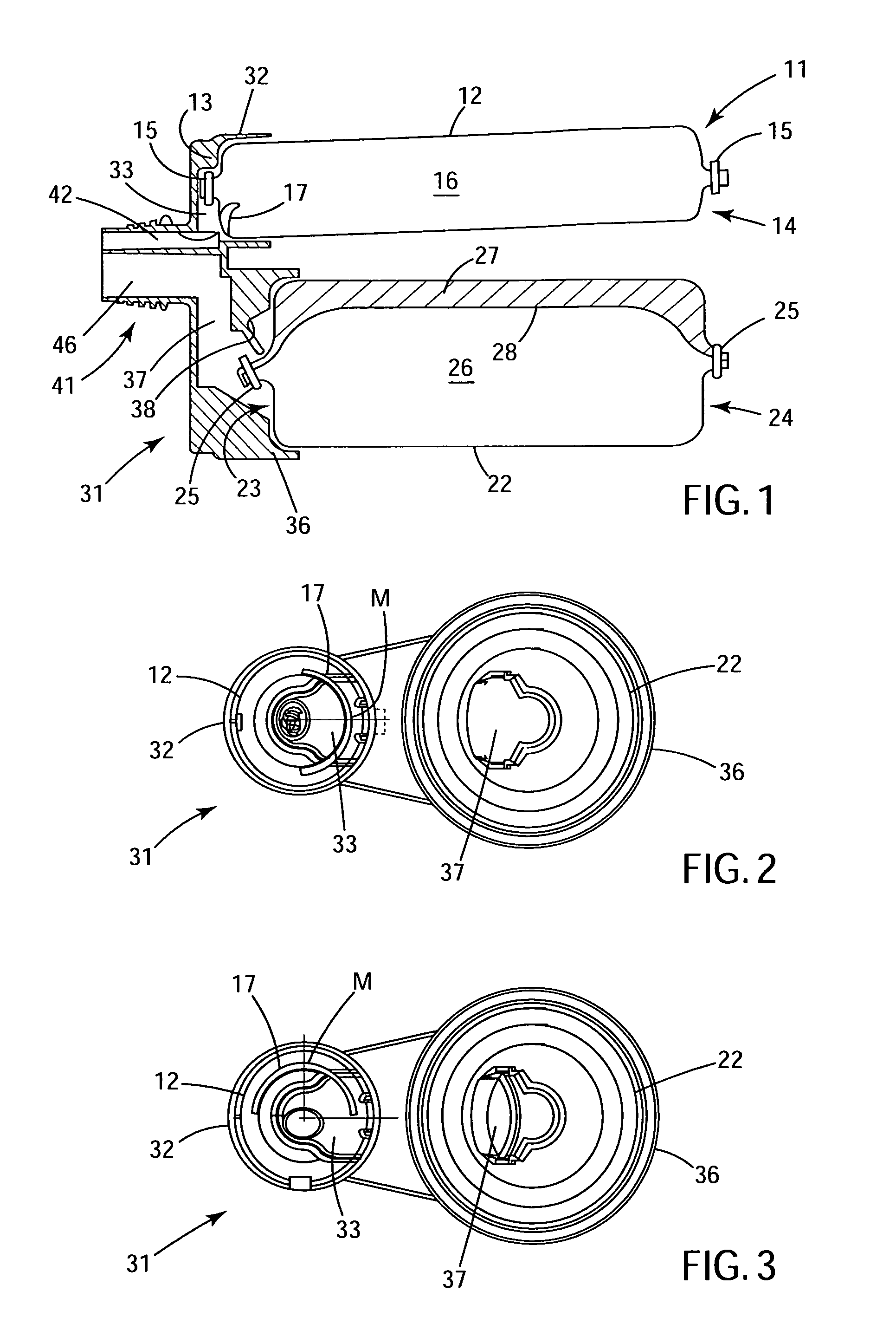
[0028]A foil container 11 according to the present invention which is shown in FIG. 1 and is designed for storing components of a multi-component mass and for being inserted in a receptacle of an ejection device, not shown, has a first foil bag 12 for a first component 16 of a three-component mass and a second foil bag 22 located near the first foil bag 12 and designed for storing a second component 26 and a third component 27 of the three-component mass separately from each other and from the first component 16. The second and third components 26, 27 are stored in separate foil bag chambers of the second foil bag 22 and which are formed by a common separation wall 28 provided in the second foil bag 22.

[0029]The first foil bag 12 is gathered at its both ends 13 and 14, with each end being closed with a clip that forms a locking element 15. The second foil bag 22 is likewise gathered at its both ends 23 and 24, with each end being closed with a clip that forms a locking element 25.

[0...


PUM


Abstract

A foil container for storing components of a multi-component mass and for being inserted in a receptacle of an ejection device, includes a first foil bag (12) that stores at least one component (16) of the multi-component mass, a second foil bag (22) arranged next to the first foil bag (12) and that stores at least two components (26, 27) of the multi-component mass separately from each other, and a head portion (31) having at least two receiving sections (32, 36) for receiving respective ends (13, 23) of the first and second foil bags (12, 22).

Description

BACKGROUND OF THE INVENTION[0001]1. Field of the Invention[0002]The present invention relates to a foil container for storing components of a multi-component mass and for being inserted in a receptacle of an ejection device and including a first bag for storing at least one component of the multi-component mass, a second foil bag arranged next to the first foil bag and for storing separate from each other, at least two components of a multi-component mass, and a head portion having at least two receiving sections for receiving respective ends of the first and second foil bags.[0003]2. Description of the Prior Art[0004]Multi-component masses such as, e.g., mortar-, foam-, and sealing masses are made available to a user in cartridges and foil containers. Foil containers have proved themselves for storing such masses and advantageously distinguish from cartridges by a smaller portion of material that need be disposed after the mass contained therein is brought out. In addition, foil co...

Claims


Application Information

Patent Timeline
Patent Type & Authority Patents(United States)
IPC IPC(8): B65D35/22
CPCB05C17/00553B05C17/00559B65D81/325B05C17/00583
Inventor WILLNER, RALFGLOGGER, JOSEFBAESSLER, ARMINTHIEMANN, FRANKBUERGEL, THOMAS
Owner HILTI AG
Why Eureka
Try Eureka