Aircraft

a technology for aircraft and support devices, applied in the field of aircraft construction, can solve the problems of difficult piloting, complexity and cost of aircraft with support devices, unsuitable for such cable landing techniques, etc., and achieve the effect of improving the reliability and useful load of aircraft and reducing costs

Active Publication Date: 2012-11-20
VASILIEVICH REDNIKOV VALERIY
View PDF16 Cites 71 Cited by
  • Summary
  • Abstract
  • Description
  • Claims
  • Application Information

AI Technical Summary

Benefits of technology

[0022]A general purpose of the present invention is to improve current techniques in the following respects: improvement of landing reliability and useful load of the aircrafts with lower cost, and also expansion of field of application (including passenger-carrier airplanes, gliders, airplane models and unmanned airplanes).

Problems solved by technology

Most types of aircrafts, including civil airplanes, glides and unmanned airplanes, do not meet these requirements, and therefore are unsuitable for such cable landing technique.
The disadvantages of this aircraft includes complexity and cost of the aircraft with a support device, a difficult piloting due to a support motion operation with a preliminary calculation of the center of gravity, and the weight of equipment aboard the aircraft.
Another disadvantages are low reliability (there is probability of a flight accident because of incorrect setting of the support) and narrow field of application of the cable landing, especially for the light unmanned aircrafts.

Method used


Image

  • Aircraft
  • Aircraft
  • Aircraft

Examples


Embodiment Construction

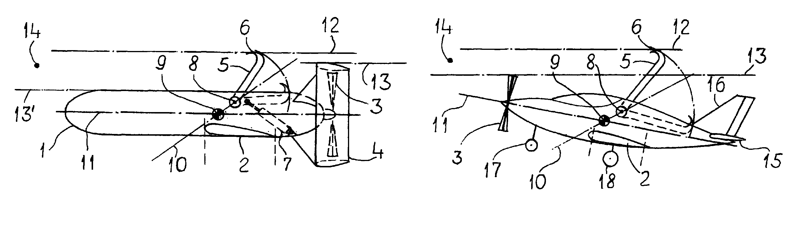
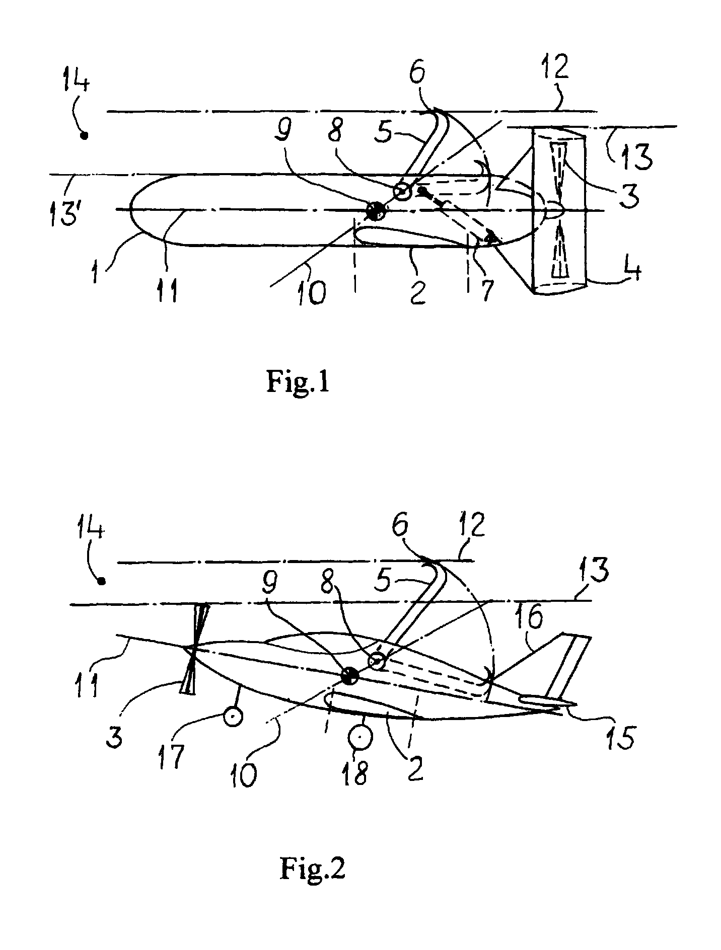
[0033]Referring now to the drawings in detail, and initially to FIG. 1, where an unmanned aircraft is built on a normal aerodynamic configuration. The aircraft has a fuselage 1 and a lifting low wing 2 located in the center fuselage. In the aft fuselage there is a pusher propeller 3 installed into a cylindrical stabilizer fin 4. Aboard the aircraft there are an arresting hook 5 with a grip portion 6, a shock-absorber 7 (for example, as in every car) and an arresting hook drive for a hook motion from the removed position (shown by dash lines) into the deployed position (shown by solid lines). This drive is not shown to avoid shading of the main elements).

[0034]The arresting hook 5 is mounted on the aircraft capable of rotating around an axis 8 (shown by a circle with a point) laying transversely of the aircraft in parallel to a body transverse (another name “lateral”) axis. Axis 8 is located within the longitudinal expanse of the mean aerodynamic chord, and above and behind the cente...


PUM


Abstract

The inventive aircraft with off-aerodrome landing consists of a body (1), a lifting wing (2) and the onboard part of a rope arresting and landing device comprising an arresting hook (5) which is provided with a grip (6). In the preferred embodiment, said aircraft is provided with a propeller (3) arranged in an annular empennage (4). Said arresting hook is arranged in such a way that it is rotatable around the transversal axis (8) of the aircraft situated in a longitudinal spacing of the aerodynamic mean chord of the wing. The aircraft leads for landing with the upwardly deployed arresting hook in such a way that the trajectory (12) of a top pickup point (6) is higher than the trajectory (13) of the highest top point of the aircraft and higher than a cable or rope (14) tensed on a landing area. The trajectory (13′) of the highest point of the aircraft located ahead of the arresting hook passes at a lower level than the cable (14). In said conditions, the grip of the arresting hook holds the cable which has a required effort for drawing it from a stationary arresting device. By overcoming said effort, the aircraft spends a flight kinetic energy and stops being suspended on the cable.

Description

CROSS-REFERENCE TO RELATED APPLICATIONS[0001]Not Applicable.STATEMENT REGARDING FEDERALLY SPONSORED RESEACH OR DEVELOPMENT[0002]Not Applicable.THE NAMES OF THE PARTIES TO A JOINT RECEACH AGREEMENT[0003]Not Applicable.INCORPORATION-BY-REFERENCE OF MATERIAL SUBMITTED ON A COMPACT DISC[0004]Not Applicable.BACKGROUND OF THE INVENTION[0005]1. Field of the Invention[0006]The present invention relates to the field of aeronautics, and more particularly to the construction of aircrafts (e.g., civil airplanes, gliders and model airplanes) with an arresting hook for a landing onto a suspended cable.[0007]2. Description of the Prior Art[0008]One group of such aircrafts is represented by the manned airplanes having an arresting hook for engagement with the cable of a cable landing device (here a term “cable” is understood any flexible element as a rope, a cable, a chain, ets.).[0009]The cable landing system (SU No. 1837038, Int.Cl.7 B 64 F 1 / 02, 30.08.90) includes a manned aircraft with an arres...

Claims


Application Information

Patent Timeline
Patent Type & Authority Patents(United States)
IPC IPC(8): B64F1/02B64C25/42B64C25/68B64D45/04B64F1/04
CPCB64C25/68B64F1/02B64F1/04B64F1/029
Inventor REDNIKOV, VALERIY VASILIEVICH
Owner VASILIEVICH REDNIKOV VALERIY
Why Eureka
Try Eureka