Grommet for wire harness

a wire harness and grommet technology, which is applied in the direction of machine supports, manufacturing tools, insulation bodies, etc., can solve the problems of difficult to restore the grommet b>1/b> and may reduce the working space, so as to improve the grommet without reducing the deformation of the stretchable portion, and prevent the reduction of the work space. , the effect of restoring the force after deformation

Inactive Publication Date: 2012-11-20
SUMITOMO WIRING SYST LTD
View PDF16 Cites 7 Cited by
  • Summary
  • Abstract
  • Description
  • Claims
  • Application Information

AI Technical Summary

Benefits of technology

[0014]Thus, the restoring ribs are provided on the convex side surface that extends in a hollow portion surrounded by the large diameter cylinder portion, instead of on the outer surface of the concave portion side of the stretchable portion being folded backward in U-shape. Therefore, the stretchable portion can have an excellent stretching-and-compressing deformability in an axial direction, in addition to a radial direction of the grommet. Further, the restoring ribs make the stretchable portion partially thicker, thereby increasing a restoring force of the stretchable portion after the deformation. Accordingly the grommet has an excellent following deformability with respect to the pulling, pushing and bending performed during a mounting operation of the grommet into the through hole in the vehicle body, or the like. Thus, a mounting operability of the grommet into the through hole in the vehicle body can be improved. At the same time, the stretchable portion does not remain in the stretched or compressed state after the following deformation, and is quickly restored to the original shape. Accordingly, the wire harness is prevented from interfering with the other components mounted on the vehicle due to the change in the path of the wire harness. Further, reduction in a work space is also prevented.
[0023]Further, at the boundary position between the small diameter cylinder portion and the stretchable portion, a step and an annular rib are respectively provided on the inner surface side and on the outer surface side, to increase the rigidity at the boundary position. Therefore, the push-in amount of the stretchable portion can be restricted, and the adhesive tape for fixing the wire harness, which is wound around the area from the outer peripheral surface of the small diameter cylinder portion to the outer peripheral surface of the wire harness, is prevented from being detached from the end portion.

Problems solved by technology

In particular, the grommet 1 is difficult to be restored after stretching or compressing deformation in the axial direction of the grommet 1.
Further, the wire harness may interfere with other components, or a working space may be reduced due to the change in the wiring path.

Method used


Image

  • Grommet for wire harness
  • Grommet for wire harness
  • Grommet for wire harness

Examples


Embodiment Construction

[0033]The particulars shown herein are by way of example and for purposes of illustrative discussion of the embodiments of the present invention only and are presented in the cause of providing what is believed to be the most useful and readily understood description of the principles and conceptual aspects of the present invention. In this regard, no attempt is made to show structural details of the present invention in more detail than is necessary for the fundamental understanding of the present invention, the description is taken with the drawings making apparent to those skilled in the art how the forms of the present invention may be embodied in practice.

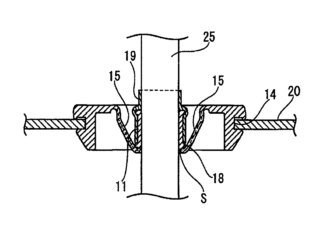
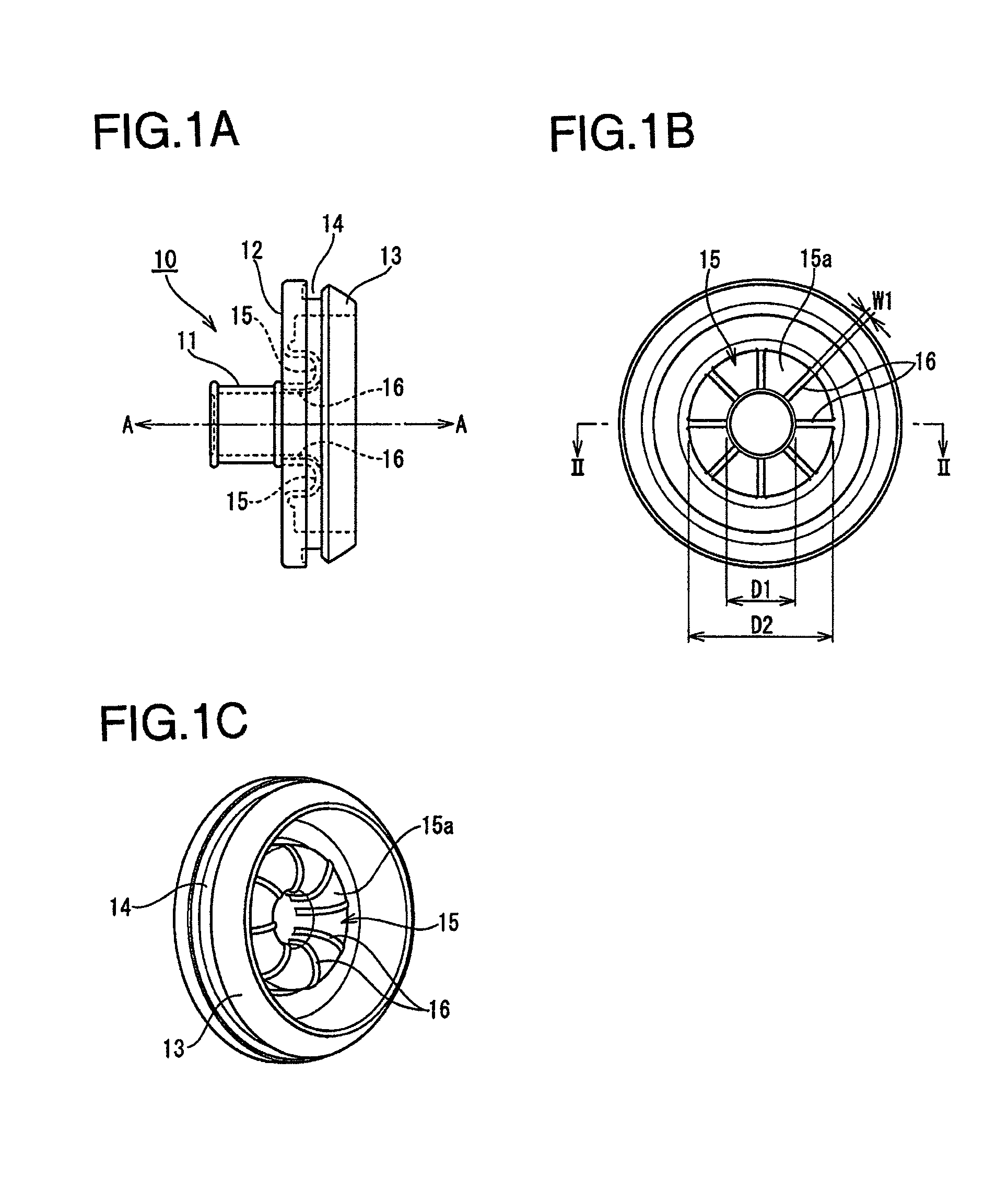
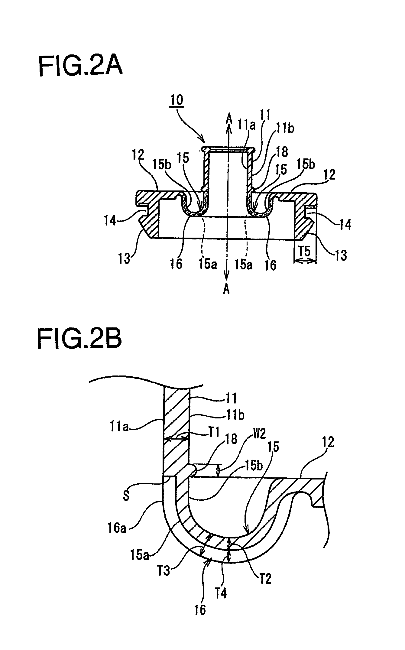
[0034]Embodiments of the present invention will be described hereinafter with respect to the drawings. FIGS. 1-3 illustrate a grommet 10 according to an embodiment of the present invention. The grommet 10 is fitted around a wire harness 25 to be inserted into a through hole 21 provided in a vehicle body panel 20 of an automobi...


PUM

PropertyMeasurementUnit
outer diameter D2aaaaaaaaaa
width W1aaaaaaaaaa

Abstract

In a grommet fitted around a wire harness wired in a vehicle, and mounted in a through hole of a vehicle body panel, a radially outward extending portion is provided on an outer peripheral surface at an end of a small diameter cylinder portion, in which the wire harness is tightly inserted. A large diameter cylinder portion is connected to an outer peripheral end of the radially outward extending portion. An annular stretchable portion is provided at a portion connecting the small diameter cylinder portion to the radially outward extending portion. A step is provided on an inner peripheral surface at a boundary position between the small diameter cylinder portion and the stretchable portion, such that a thickness of the stretchable portion is thinner than a thickness of the small diameter cylinder portion. An annular rib is provided on an outer peripheral surface of the boundary position. Radially extending restoring ribs are provided on a convex side surface of the stretchable portion circumferentially spaced in-between.

Description

CROSS-REFERENCE TO RELATED APPLICATIONS[0001]The present application claims priority under 35 U.S.C. §119 of Japanese Application No. 2010-030511, filed on Feb. 15, 2010, the disclosure of which is expressly incorporated by reference herein in its entirety.BACKGROUND OF THE INVENTION[0002]1. Field of the Invention[0003]The present invention is related to a grommet for a wire harness, in particular, to a grommet, into which a wire harness to be wired in an automobile is inserted and which is mounted in a through hole of a vehicle body panel, having an improved following deformability and a restoring force after deformation of the grommet.[0004]2. Description of Related Art[0005]Conventionally, when a wire harness wired in an automobile is inserted into a through hole of a vehicle body panel, a grommet, into which the wire harness is inserted, is mounted in the through hole of the vehicle body panel, and thus, the grommet protects a portion of the wire harness W / H passing through the ...

Claims


Application Information

Patent Timeline
Patent Type & Authority Patents(United States)
IPC IPC(8): H01B17/26
CPCB60R16/0222H02G3/22Y10T16/05
Inventor FUJITA, TETSUYA
Owner SUMITOMO WIRING SYST LTD
Why Eureka
Try Eureka