Coupled line filter and arraying method thereof

a filter and line array technology, applied in the field of coupled line filters, can solve the problems of low quality coefficient (q) affecting the insertion loss of the inter-digital filter, the filter is an obstacle to miniaturization and cost reduction of the wireless communication system, and the filter is limited in the realization of a filter having broadband characteristics, etc., to achieve the effect of low insertion loss

Inactive Publication Date: 2012-11-20
ELECTRONICS & TELECOMM RES INST
View PDF17 Cites 18 Cited by
  • Summary
  • Abstract
  • Description
  • Claims
  • Application Information

AI Technical Summary

Benefits of technology

[0016]An embodiment of the present invention is directed to providing a coupled line filter having broadband characteristics and low insertion loss.

Problems solved by technology

The filter has been an obstacle to miniaturization and cost reduction of the wireless communication system.
However, the resonator filter with a phase of approximately 90° transmission lines is rarely used to get low insertion losses in mm wave region because the resonator filter has a low quality coefficient when the coefficient filter uses a transmission line between the top and bottom surfaces that are grounded.
However, the disclosed technologies has small number of coupling between resonators and the coupling amount between input / output port and a resonator is very small, there is a limitation in realizing a filter having broadband characteristics.
Also, when the resonators become short, the quality coefficient (Q) affecting the insertion loss of the inter-digital filter becomes low.
However, when a coupled line filter is formed using the line resonators having an electrical length of 270°, there is a problem of a pass band being formed in a low frequency band, which is not desired by a user.

Method used


Image

  • Coupled line filter and arraying method thereof
  • Coupled line filter and arraying method thereof
  • Coupled line filter and arraying method thereof

Examples


first embodiment

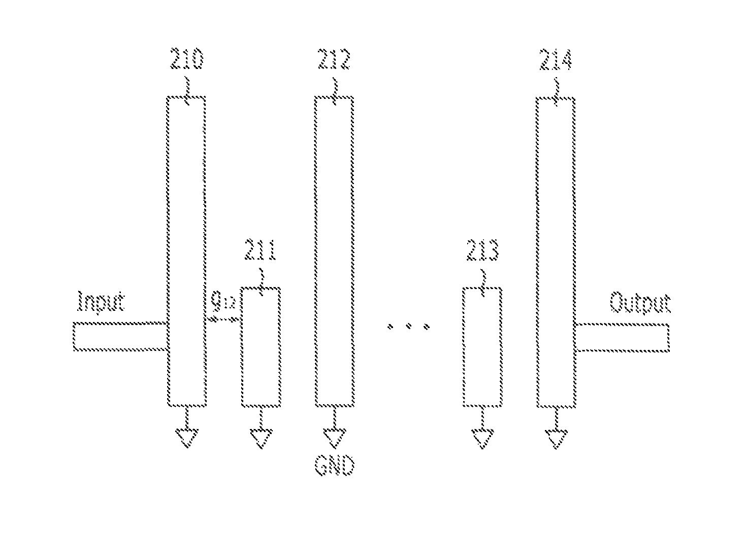
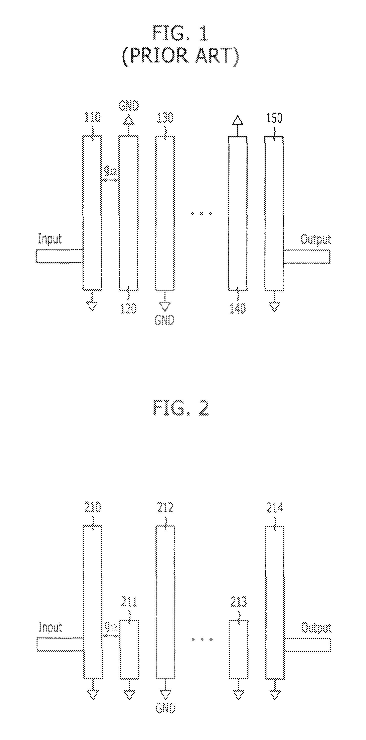
[0036]FIG. 2 describes a coupled line filter in accordance with the present invention.

[0037]Referring to FIG. 2, the coupled line filter of the first embodiment of the present invention includes an input line, an output line, and a plurality of line resonators 210, 211, 212, . . . , 213, and 214.

[0038]The input line is directly connected to the first line resonator 210, and the output line is directly connected to the last line resonator 214. The number of the line resonators 210, 211, 212, . . . , 213, and 214 is determined based on the order desired by a user. When a user wants to design a 3-order coupled line filter, the coupled line filter is realized with three line resonators.

[0039]Also, each of the line resonators 210, 211, 212, . . . , 213, and 214 has a width determined based on the design value and the line resonators 210, 211, 212, . . . , 213, and 214 are disposed in parallel. However, as illustrated in FIG. 2, the lengths of the line resonators 210, 211, 212, . . . , 21...

second embodiment

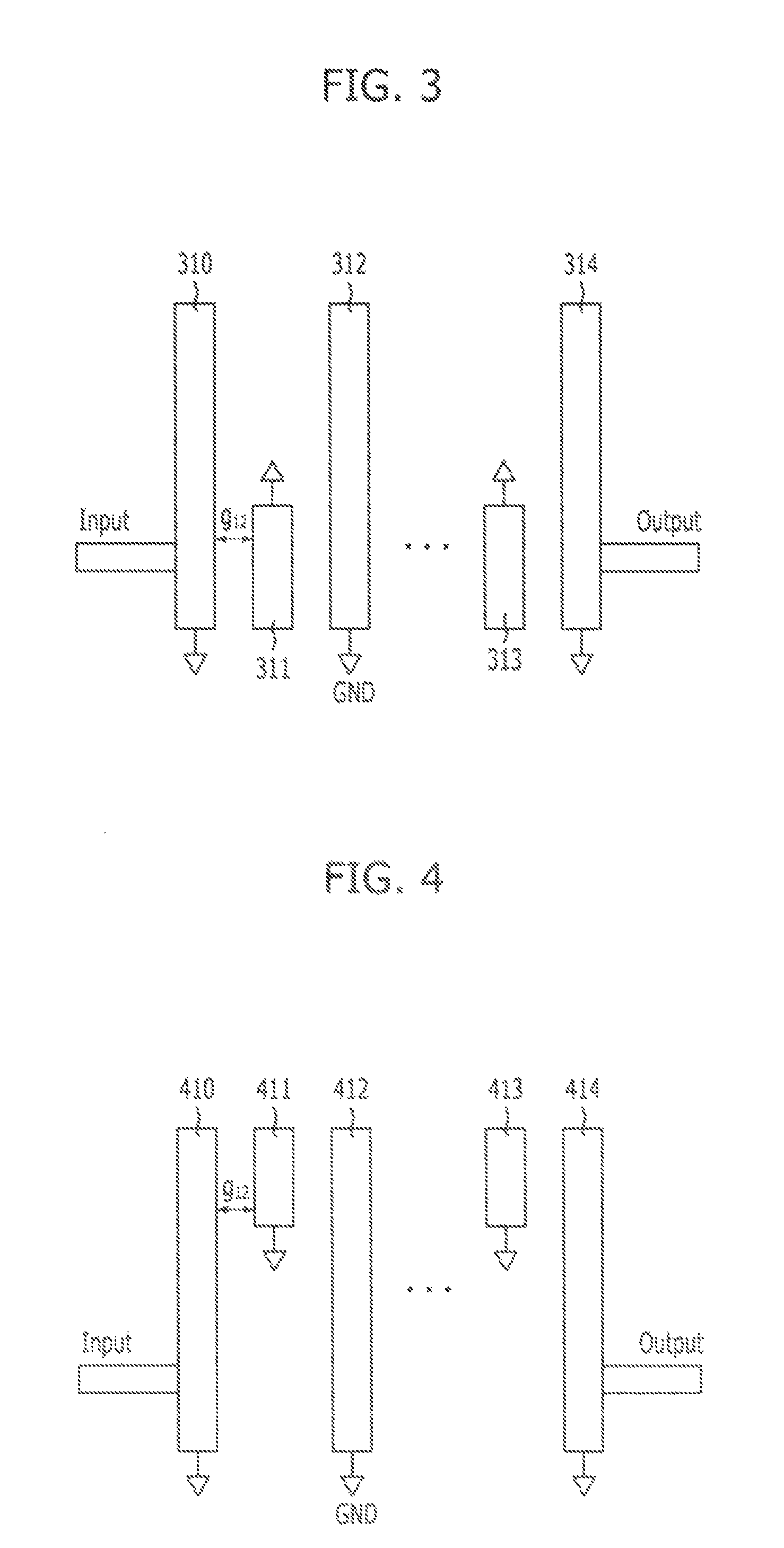
[0044]FIG. 3 describes a coupled line filter in accordance with the present invention.

[0045]Referring to FIG. 3, the coupled line filter of the second embodiment of the present invention has a similar structure to the coupled line filter of the first embodiment illustrated in FIG. 2. The difference between the two coupled line filters is that the coupled line filter of the second embodiment has a grounding direction of the line resonators 310, 311, 312, . . . , 313, and 314 which is different from the grounding direction of the line resonators 210, 211, 212, . . . , 213, and 214. In other words, among the multiple line resonators 310, 311, 312, . . . , 313, and 314, the even number-placed line resonators 311, . . . , 313 have the other side grounded. Here, the other side of the even number-placed line resonators 311, . . . , 313 means the side where the odd number-placed line resonators 310, 312, . . . , 314 are not disposed.

[0046]The embodiments of the present invention illustrated...

third embodiment

[0047]FIG. 4 describes a coupled line filter in accordance with the present invention.

[0048]Referring to FIG. 4, the coupled line filter of the third embodiment of the present invention is similar to the coupled line filter of the first embodiment shown in FIG. 2. The difference between the two coupled line filters is that the even number-placed line resonators 211, . . . , 213 of the coupled line filter of the first embodiment shown in FIG. 2 are disposed on one side of the odd number-placed line resonators 210, 212, . . . , 214, while the even number-placed line resonators 411, . . . , 413 of the coupled line filter of the third embodiment shown in FIG. 4 are disposed on the other side of the odd number-placed line resonators 410, 412, . . . , 414. The even number-placed line resonators 411, . . . , 413 of the coupled line filter of the third embodiment shown in FIG. 4 are grounded in a direction toward the side of the odd number-placed line resonators 410, 412, . . . , 414 where ...


PUM


Abstract

A coupled line filter includes: a first line resonator connected input port and a second line resonator connected with output port each having an electrical length of 270° at a predetermined center frequency, the first and second line resonators being disposed parallel to each other; and a third line resonator including one or more line resonators disposed between the first line resonator and the second line resonator, each line resonator having an electrical length of 90° at the center frequency and a first side aligned with first sides of the first line resonator and the second line resonator, wherein an order of the coupled line filter is determined by summing the number of the line resonators included in the third line resonator and the first and second line resonators.

Description

CROSS-REFERENCES TO RELATED APPLICATIONS[0001]The present invention claims priority of Korean Patent Application Nos. 10-2008-0124650 and 10-2009-0022531, filed on Dec. 9, 2008, and Mar. 17, 2009, respectively, which are incorporated herein by reference.BACKGROUND OF THE INVENTION[0002]1. Field of the Invention[0003]The present invention relates to a coupled line filter; and, more particularly, to a coupled line filter usable in high frequency band.[0004]2. Description of Related Art[0005]Very high frequency is drawing attention as a radio frequency band favorable for using broadband signals and processing data at high speed. Specifically, frequency bands over 60 GHz are preferred and studied in both domestic and overseas countries to develop components and systems therefore. Also, to minimize the size of components and reduce the costs, Low-Temperature Co-fired Ceramic (LTCC) technology for three-dimensional integration is applied thereto.[0006]Meanwhile, one of the essential compo...

Claims


Application Information

Patent Timeline
Patent Type & Authority Patents(United States)
IPC IPC(8): H01P1/203
CPCH01P1/20336
Inventor UHM, MAN-SEOKNOH, YOUN-SUBKWAK, CHANGSOOYUN, SO-HYEUNAHN, KIBURMYOM, IN-BOK
Owner ELECTRONICS & TELECOMM RES INST
Why Eureka
Try Eureka