Force measurement system having inertial compensation

a technology of inertial compensation and force measurement, which is applied in the direction of force/torque/work measurement apparatus, instruments, applications, etc., can solve the problems of undesirable measurement errors, inability to rigidly affix the force measurement device to the ground on which it is supported, and the force measurement plate used to conduct the dynamic testing of human subjects cannot be rigidly affixed to any support surface. , to achieve the effect of accurate force measurement and accurate force measuremen

Active Publication Date: 2012-11-20
BERTEC
View PDF45 Cites 88 Cited by
  • Summary
  • Abstract
  • Description
  • Claims
  • Application Information

AI Technical Summary

Benefits of technology

[0012]A first object of the present invention is to provide a force measurement system with inertial compensation that is capable of accurately compensating for the non-inertial characteristics of a large measurement system which undergoes complex motions.
[0047]In yet another preferred embodiment, the data acquisition device further includes: a data processing device, the data processing device configured to receive the measured quantity that is representative of the forces and / or moments being applied to the surface of the force measurement assembly by the subject, and to convert the measured quantity into output forces and / or moments. In this preferred embodiment, the data processing device uses the acceleration measured by the at least one accelerometer to correct the output forces and / or moments so as to provide a more accurate measurement of the forces and / or moments being applied to the surface of the force measurement assembly by the subject.

Problems solved by technology

However, in many applications, it is either impossible and / or undesirable to rigidly affix the force measurement device to the ground on which it is supported.
For example, a force measurement plate used to conduct the dynamic testing of human subjects cannot be rigidly affixed to any support surface.
In such instances, it cannot be accurately assumed that the force measurement device is part of an inertial system, and it is necessary to compensate for the forces produced by the movement of the force measurement device, which results in undesirable measurement errors.
While an analytical approach can be used for simple systems wherein the motion is limited to one direction, an analytical approach will not produce sufficiently accurate results for large systems that undergo complex multi-dimensional motion.

Method used


Image

  • Force measurement system having inertial compensation
  • Force measurement system having inertial compensation
  • Force measurement system having inertial compensation

Examples


first embodiment

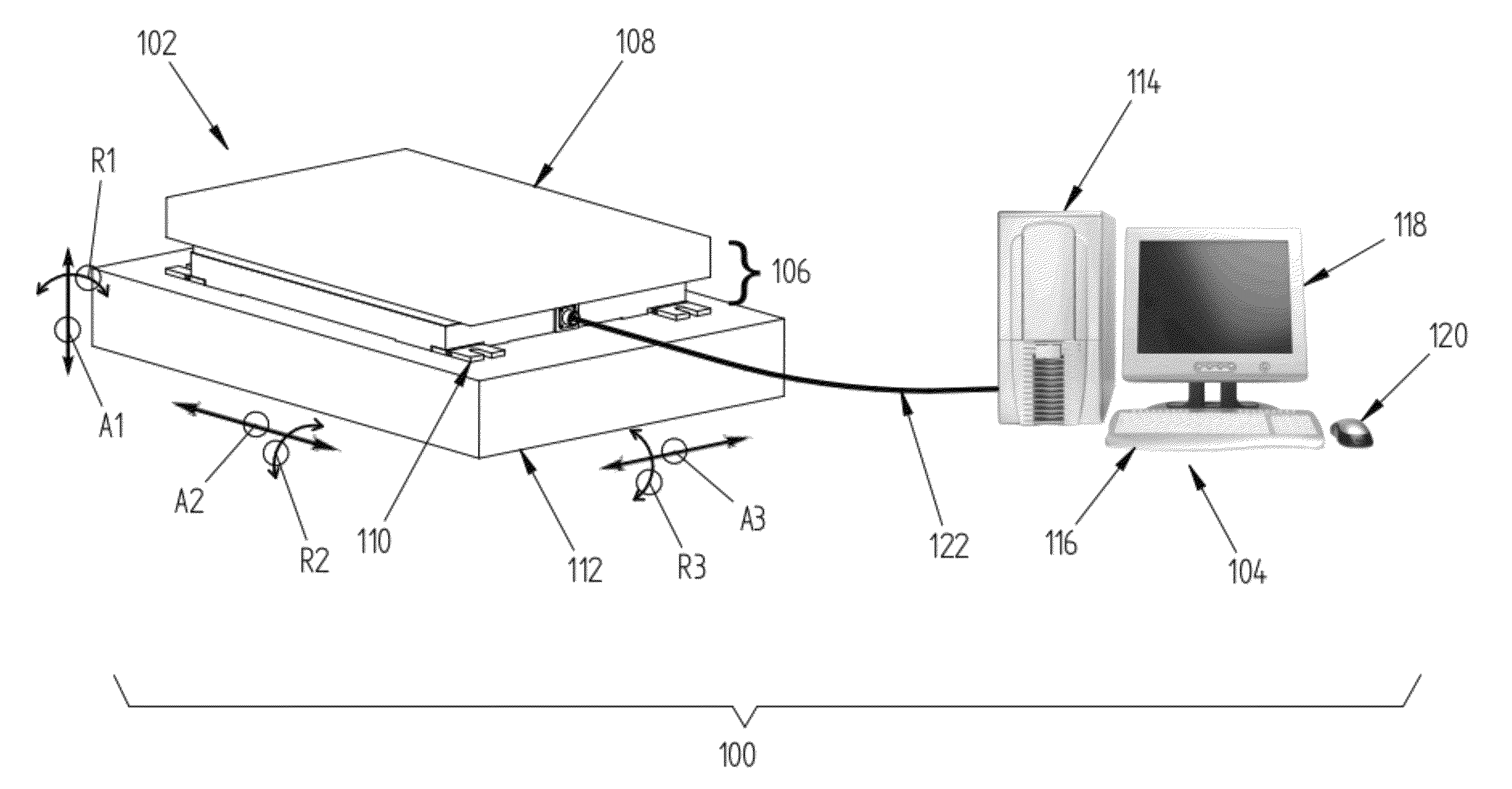
[0067]Referring again to FIG. 1, it can be seen that the force measurement assembly 102 according to the invention, includes a force plate or platform 106 that is attached to the top of a motion base 112 via a plurality of mounting brackets 110. The force plate or platform 106 has a top surface 108 that is configured to receive at least one portion of a body of a subject. In a preferred embodiment, a subject stands in an upright position atop the force plate 106 and the feet of the subject are placed on its top surface 108. In FIG. 1, the arrows A1, A2, A3 disposed adjacent to the motion base 112 schematically depict the displaceable nature of the force measurement assembly 102, which is effectuated by the motion base 112. Moreover, the curved arrows R1, R2, R3 in FIG. 1 schematically illustrate the ability of the force measurement assembly 102 to be rotated about a plurality of different axes, the rotational movement of the force measurement assembly 102 is also generated by the mo...

second embodiment

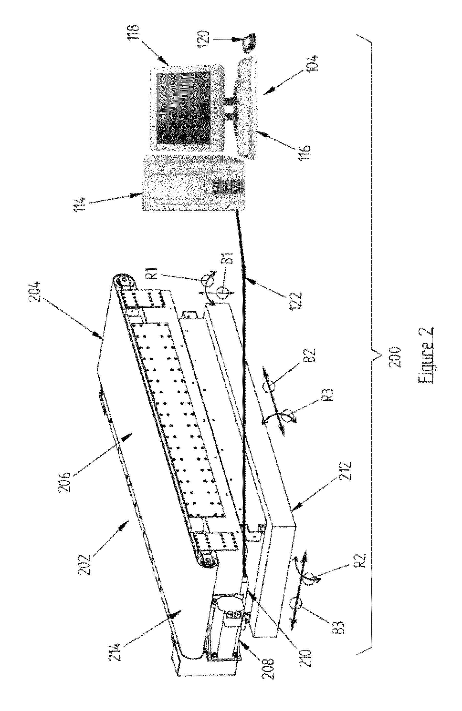
[0070]As illustrated in FIG. 2, the force measurement assembly 202 according to the invention includes a treadmill 204 that is attached to the top of a motion base 212. The treadmill 204 has a top surface 206 that is configured to receive at least one portion of a body of a subject. In a preferred embodiment, a subject walks or runs in an upright position atop the treadmill 204 with the feet of the subject contacting the top surface 206 of the treadmill 204. The belt 214 of the treadmill 204 is rotated by an electric actuator assembly 208, which generally comprises an electric motor. The electrical cable 122 is operatively coupled to a load output device 210, which is at one end of the treadmill 204, and beneath the rotating belt 214. While it is not readily visible in FIG. 2 due to its internal location, the force measurement assembly 202, like the force measurement assembly 102, includes a force plate 106 with a plurality of force transducers disposed below the top surface 206 of ...


PUM


Abstract

A force measurement system having inertial compensation includes a force measurement assembly with at least one accelerometer configured to measure the acceleration thereof. According to one aspect of the invention, the force measurement system additionally includes at least one angular velocity sensor configured to measure the angular velocity of the force measurement assembly. According to another aspect of the invention, the force measurement system additionally includes a data processing device with a computer-readable medium loaded thereon that is configured to execute a calibration procedure for determining the inertial parameters of the force measurement assembly by utilizing the measured acceleration of the force measurement assembly while the force measurement assembly is subjected to a plurality of applied linear and / or rotational motion profiles. According to still another aspect of the invention, the at least one accelerometer is disposed on the force transducer.

Description

CROSS-REFERENCE TO RELATED APPLICATIONS[0001]Not Applicable.STATEMENT REGARDING FEDERALLY SPONSORED RESEARCH OR DEVELOPMENT[0002]Not Applicable.NAMES OF THE PARTIES TO A JOINT RESEARCH AGREEMENT[0003]Not Applicable.INCORPORATION BY REFERENCE OF MATERIAL SUBMITTED ON A COMPACT DISK[0004]Not Applicable.BACKGROUND OF THE INVENTION[0005]1. Field of the Invention[0006]The invention generally relates to force and / or moment measurement systems. More particularly, the invention relates to force and / or moment measurement systems with inertial compensation.[0007]2. Description of Related Art[0008]Force measurement systems are utilized in various fields to quantify the reaction forces and moments exchanged between a body and support surface. For example, in biomedical applications, force measurement systems are used for gait analysis, assessing balance and mobility, evaluating sports performance, and assessing ergonomics. In order to quantify the forces and moments resulting from the body disp...

Claims


Application Information

Patent Timeline
Patent Type & Authority Patents(United States)
IPC IPC(8): G01G23/01
CPCA61B5/1036G01L5/16G01M1/122A61B5/112A61B5/224A61B2562/0219
Inventor BERME, NECIPGULER, HASAN CENK
Owner BERTEC
Why Eureka
Try Eureka