Ladder safety device and method of using the same

a safety device and ladder technology, applied in the direction of scaffold accessories, constructions, building aids, etc., can solve the problems of movable jaws from the fixed jaw away from the fixed jaw and the inability of the one-way drive member to move the slide bar

Inactive Publication Date: 2012-11-27
RUDD DAVID MICHAEL
View PDF19 Cites 14 Cited by
  • Summary
  • Abstract
  • Description
  • Claims
  • Application Information

AI Technical Summary

Benefits of technology

[0005]It is an object of Applicant's present invention to provide a bar clamp wherein the movable jaw may be moved over a long distance rapidly and which may then incrementally and precisely be advanced tightly against building structure captured between the fixed and moving jaw.
[0006]It is another object of Applicant's present invention to provide for a ladder stabilizing device that is quick and easy to install without tools, easy to put on and remove, requiring a minimum of adjustment, and that is compact and portable.
[0007]It is another object of Applicant's present invention to provide a ladder stabilizing device that does not get in the way of the user climbing the ladder and is adjustable to fit different sized ladders and structures.
[0008]It is yet another object of Applicant's present invention to provide for an improved, quick action clamp, where the clamp operation may be accomplished with a minimum of manual manipulation.
[0011]More specifically, Applicant provides a house clamp assembly having a fixed jaw and a slide bar mounted movable jaw, the fixed jaw opposing the movable jaw. A one-way drive member, by operation of a trigger handle grip, releasably engages the slide bar and advances the movable jaw towards the fixed jaw. The one-way drive member is incapable of moving the slide bar and movable jaw away from the fixed jaw. A return motion of the movable jaw (separating) is accomplished manually when the one-way drive member is disengaged. A braking lever, which is biased against the slide bar, prevents reverse motion of the slideable jaw away from the fixed jaw, except when the first lever is disengaged from the slide bar.

Problems solved by technology

The one-way drive member is incapable of moving the slide bar and movable jaw away from the fixed jaw.

Method used


Image

  • Ladder safety device and method of using the same
  • Ladder safety device and method of using the same
  • Ladder safety device and method of using the same

Examples


first embodiment

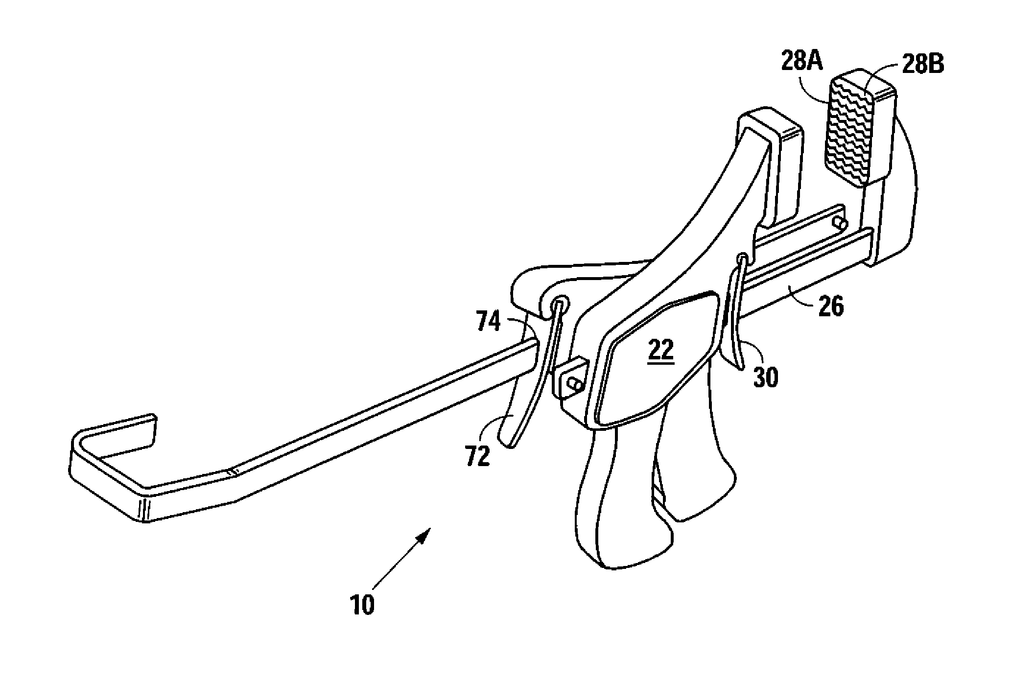
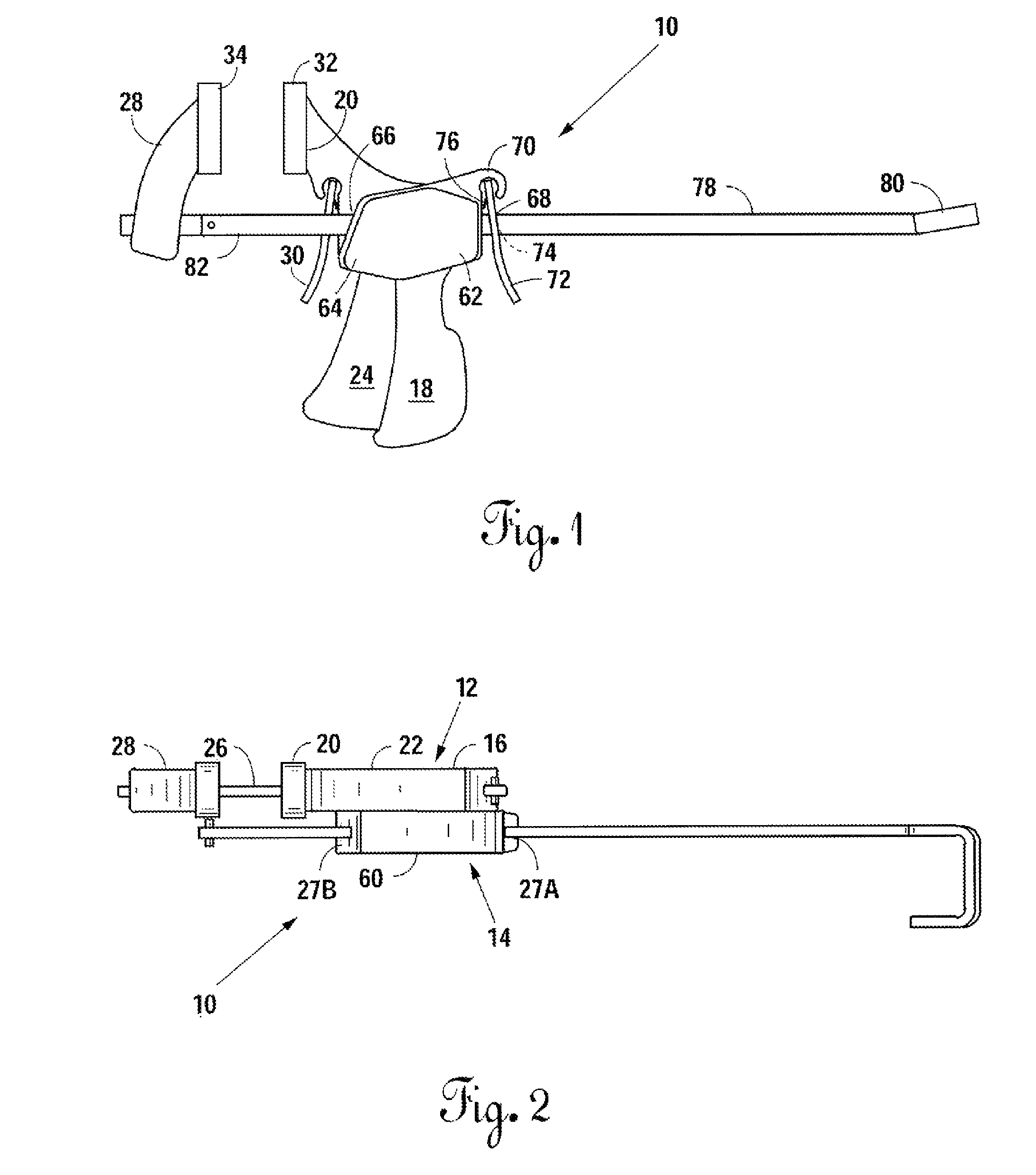
[0023]FIGS. 1-5 illustrate Applicant's novel ladder stabilizing device 10. A ladder stabilizing device 10 is seen to be comprised of two assemblies, a house clamp assembly 12 and a ladder hook assembly 14. The house clamp assembly 12 is designed to fixedly engage the ladder stabilizing device 10 to a part of a house H, typically a depending board sometimes referred to as a fascia board S (see FIGS. 3A and 3B). The ladder hook assembly 14 is designed to engage a ladder L, typically along the rail R thereof (see FIGS. 3A and 3B). By having a portion of the ladder stabilizing device 10 that will fixedly and rigidly engage a part of a building, and a ladder hook assembly that will couple to a portion of a ladder, such as a ladder rung or a ladder rail, one can stabilize a ladder L against a building or other structure, such as a fascia board, so the two are positively engaged, thus avoiding a possible inadvertent movement of the ladder with respect to the building.

[0024]It is seen with ...

third embodiment

[0034]With respect to FIGS. 9A, 9B, and 10, Applicant provides a third embodiment, including a modification to ladder engaging end 80 of hooked slide member 78. More specifically FIGS. 9A, 9B, and 10 illustrate a pivoting ladder engaging member 84, which articulates on hooked slide member 78 with a pin 86. This modification may be useful, as seen in FIG. 10, as it will tend to provide a broader contact surface with the rail and will angularly adjust to the angle that the rail of the ladder makes with respect to the building structure.


PUM


Abstract

A house clamp assembly having a fixed jaw and a slide bar mounted movable jaw, the fixed jaw opposing the movable jaw. A one-way drive means, by operation of a trigger handle grip, releasably engages the slide bar and advances the movable jaw towards the fixed jaw. The one-way drive means is incapable of moving the slide bar and movable jaw away from the fixed jaw. A return motion of the movable jaw (separating) is accomplished manually when the one-way drive means is disengaged. A braking lever, which is biased to bind the slide bar, prevents reverse motion of the slideable jaw away from the fixed jaw, except when the first lever is disengaged from the slide bar. A device for securing a ladder to a building, wherein the removed end of the slide member has a hook shape; wherein the jaws include jaw faces having multiple raised portions, wherein the releasable braking means of the building clamp assembly means includes a pivoting lever; wherein the locking member of the ladder hook assembly includes a pivoting lever, attached at one end to the body, and having a slot dimensioned to slideably receive the hook slide member therethrough; wherein the body of the ladder hook assembly includes a pair of slots dimensioned for and adapted to slideably receive the slide member therethrough; and wherein the slots are arranged to maintain the hook slide member substantially parallel to the slide bar of the building clamp assembly.

Description

[0001]This is a utility application which claims priority from, the benefit of, and incorporates by reference, provisional patent application Ser. No. 61 / 127,515, filed May 14, 2008.FIELD OF THE INVENTION[0002]This invention relates to an improved ladder safety device that is adapted to be fixedly engaged to a fascia board or other structure on a building in a safe and stable manner, following which the ladder is engaged to the device for secure maintenance of the ladder against the building structure.BACKGROUND OF THE INVENTION[0003]Ladder stabilizing devices are designed to reduce accidents. Some ladder stabilizing devices are positively clamped to a portion of a ladder, such as a rung or a rail, and then allowed to passively engage a portion of a building structure. Other ladder stabilizing devices may positively clamp to and affix against a building structure and positively and releasably clamp to a portion of the ladder.[0004]The present invention has been devised to avoid cert...

Claims


Application Information

Patent Timeline
Patent Type & Authority Patents(United States)
IPC IPC(8): E06C7/48
CPCE06C7/48
Inventor RUDD, DAVID MICHAEL
Owner RUDD DAVID MICHAEL
Why Eureka
Try Eureka