Valve assembly for damper between a lower chamber and a compensation chamber in the damper

a valve assembly and damper technology, applied in the direction of mechanical equipment, functional valve types, shock absorbers, etc., can solve the problems of increasing complicated production of the base, and increasing the complexity of the valve assembly, so as to increase the dimensions of the base and the production of the base. the effect of complicated base production

Active Publication Date: 2012-11-27
ALSTOM TRANSPORT TECH SAS
View PDF12 Cites 1 Cited by
  • Summary
  • Abstract
  • Description
  • Claims
  • Application Information

AI Technical Summary

Benefits of technology

[0008]Such valve assemblies are complicated to produce and assemble. The presence of a groove makes the production of the base more complicated and increases the dimensions of this base. In addition, during assembly the operator is required to insert the holding device into the groove by exerting manual pressure on this device so as to pre-tension it and fit it into the groove. This operation requires a considerable amount of pressure, especially if the diameter of the base is small. During this operation, the holding device is folded and may thus become twisted or deformed, which may lead to the valve malfunctioning during use. There is also the risk of the operator being injured when assembling the valve assembly.
[0009]One of the objects of the invention provides a valve assembly which is simple to assemble and produce and with smaller dimensions.
[0011]Since the elastic holding device is located beneath the base, it is no longer necessary to provide a groove on the base. The dimensions of the base may be reduced and it may be easier to assemble, since the holding device can simply be fixed to the valve holder and positioned beneath the base, without the need to exert pressure on the device and fit it in the base. The risk of the holding device becoming deformed may also be reduced.

Problems solved by technology

Such valve assemblies are complicated to produce and assemble.
The presence of a groove makes the production of the base more complicated and increases the dimensions of this base.
This operation requires a considerable amount of pressure, especially if the diameter of the base is small.
During this operation, the holding device is folded and may thus become twisted or deformed, which may lead to the valve malfunctioning during use.
There is also the risk of the operator being injured when assembling the valve assembly.

Method used


Image

  • Valve assembly for damper between a lower chamber and a compensation chamber in the damper
  • Valve assembly for damper between a lower chamber and a compensation chamber in the damper
  • Valve assembly for damper between a lower chamber and a compensation chamber in the damper

Examples


Embodiment Construction

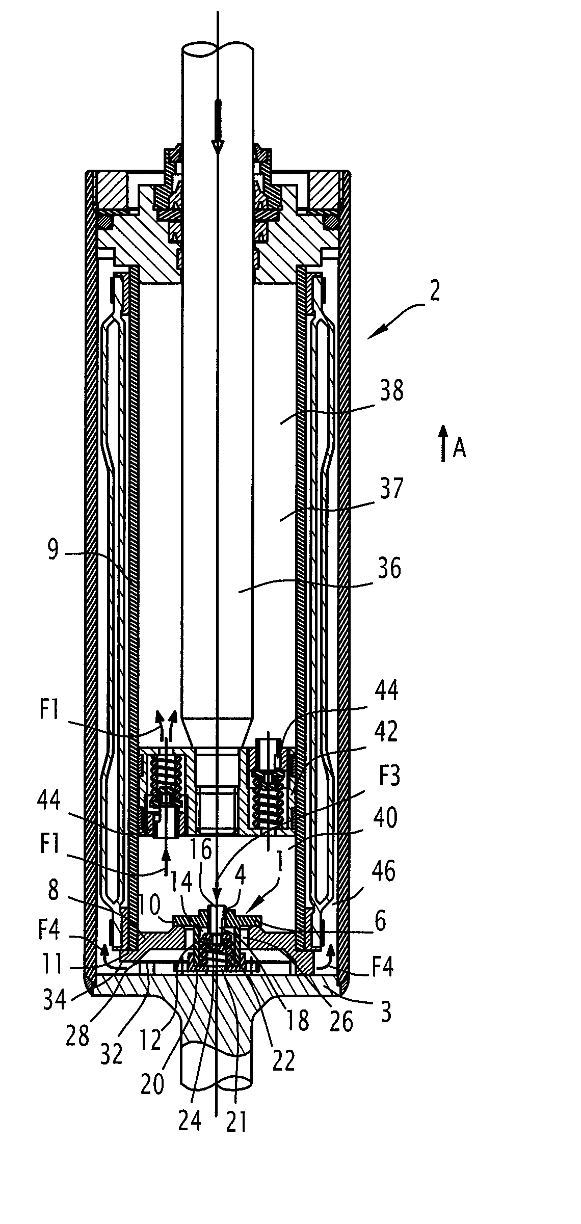
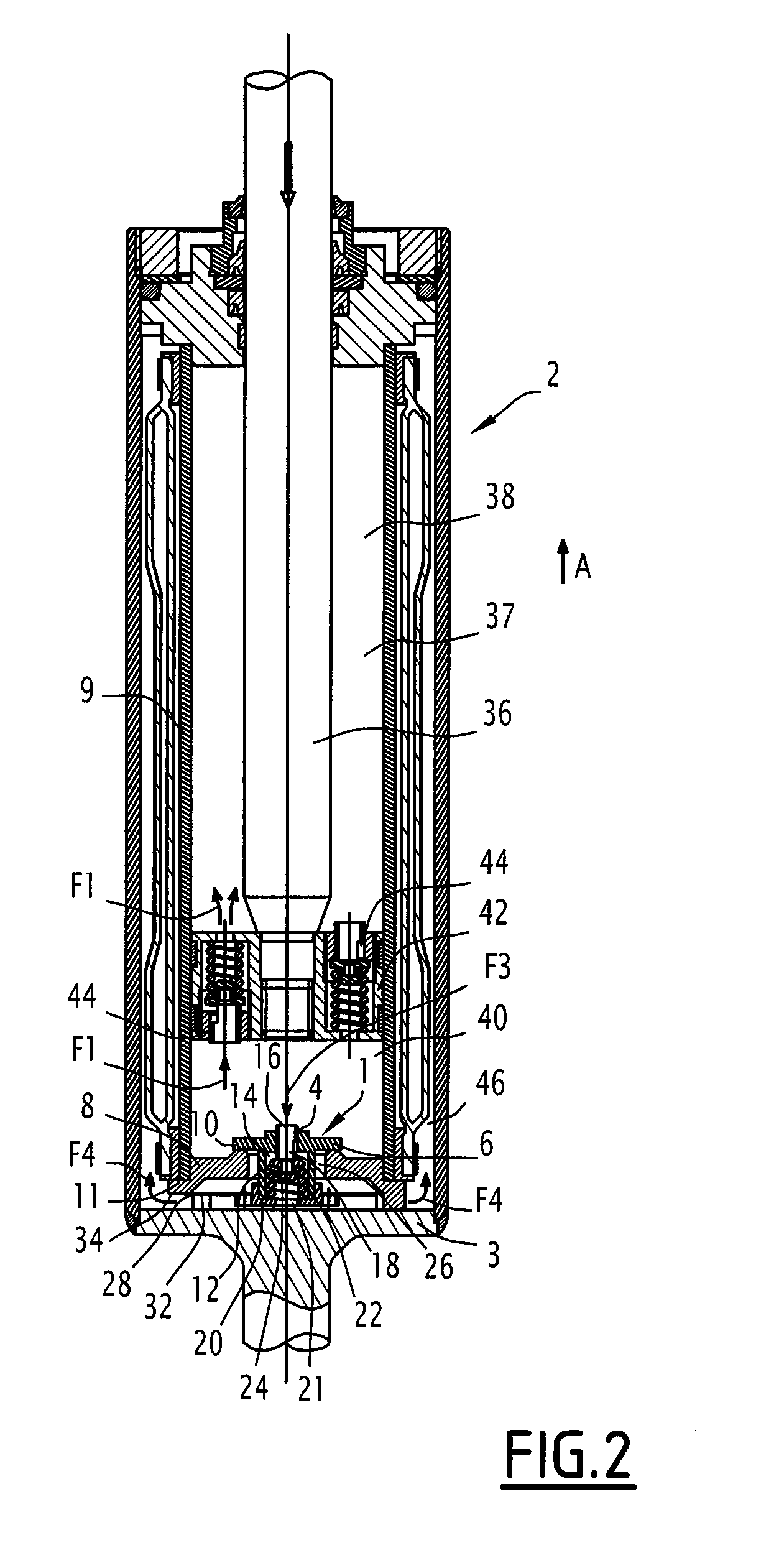
[0025]In the description, the terms “upper”, “lower”, “beneath” and “above”, etc. are defined with reference to a damper assembled as shown on FIGS. 2 and 3, the direction of elevation being shown by arrow A on these figures.

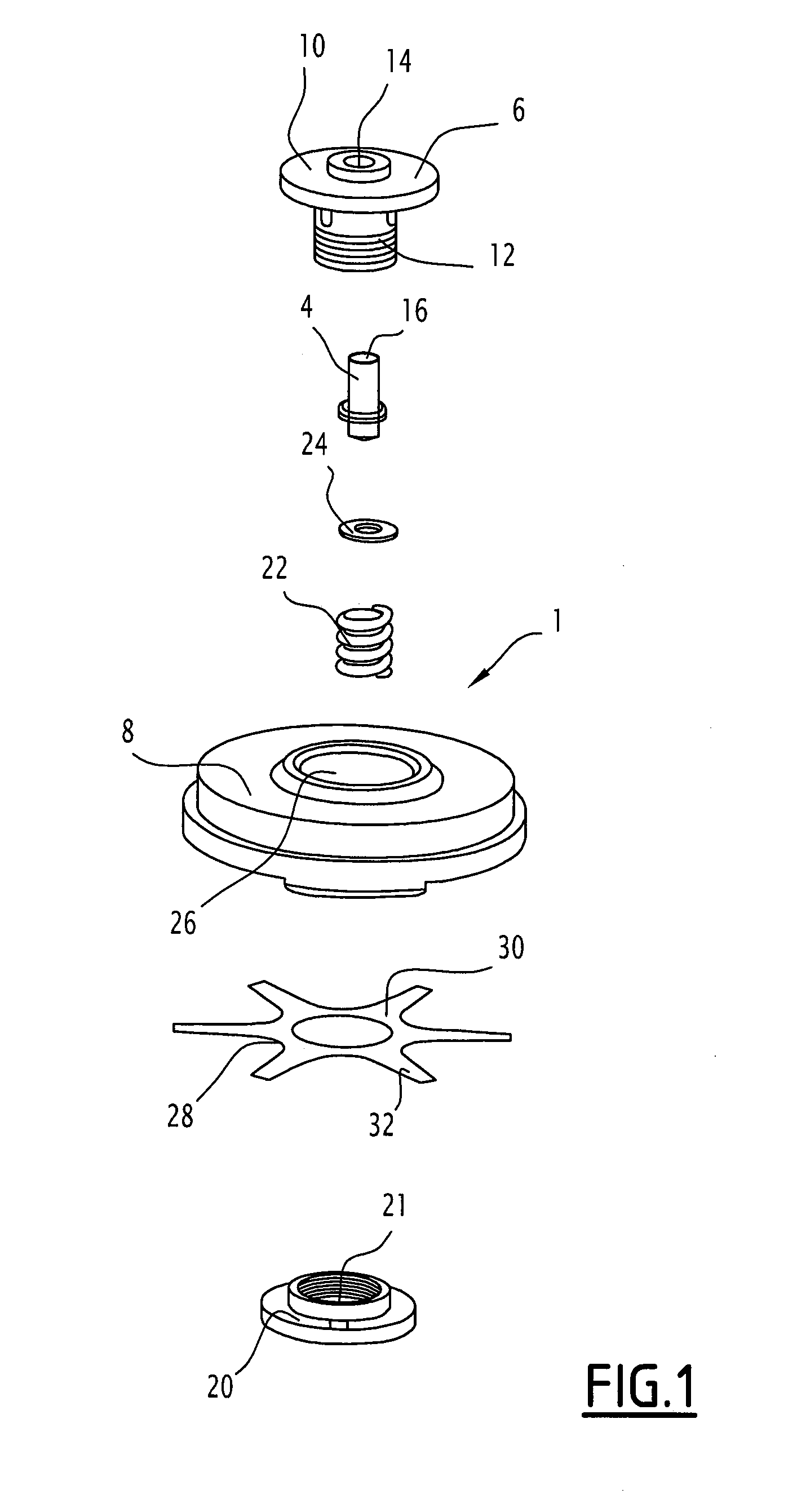
[0026]With reference to FIG. 1 we describe a valve assembly 1 for a damper 2 comprising a valve 4 which slides in a valve holder 6 and a base 8 intended to be supported on the bottom of the damper 2.

[0027]As shown in FIGS. 2 and 3, the base 8 is located between the lower part of the tube 9 defining the limits of the volume of the chamber 37 of the damper and the bottom 3 of the damper 2. The tube 9 rests on an annular rim 11 formed on the upper face of the base 8, while the lower face 34 of the base 8 rests on the bottom of the damper 2. The operation of this damper 2 in relation to the valve assembly 1 will be described subsequently.

[0028]As shown in FIG. 1, the valve holder 6 comprises a seat 10 and a body 12 extending from the seat 10 beneath the seat to the ...


PUM


Abstract

A valve assembly is provided. The valve assembly includes a valve sliding in a valve holder and a base. The valve holder is held by the base by a resilient holding mechanism, the valve holder is mobile with respect to the base between a compression position and an expansion position. The valve holder includes a seat and a body extending beneath the seat and extending into the base. The holding mechanism is fixed on the one hand to the body of the valve holder and includes at least one portion extending beneath the lower face of the base, the portion resting against the lower face when the valve holder is in the expansion position. A damper is also provided.

Description

[0001]This claims the benefit of French Patent Application No. 08 56631, filed on Oct. 1, 2008 and hereby incorporated by reference herein.[0002]The present invention relates to a valve assembly for a damper of the type comprising a valve sliding in a valve holder and a base intended to be supported on the bottom of the damper.[0003]The present invention also relates to a damper comprising such a valve assembly.BACKGROUND[0004]In a damper, a piston rod and a piston are able to move within a chamber which may, for example, be filled with oil, separated by the piston into an upper chamber and a lower chamber. The piston is able to move between a compression position and an expansion position. In the compression phase the oil passes from the lower chamber to the upper chamber and in the expansion phase the oil passes from the upper chamber to the lower chamber. In the compression phase the piston rod and the piston move down into the chamber and thus reduce the available volume inside ...

Claims


Application Information

Patent Timeline
Patent Type & Authority Patents(United States)
IPC IPC(8): F16F9/34
CPCF16F9/34F16F9/32
Inventor MARTIN, MICHELDUCAROUGE, GUYSCHMUTZ, FRANCOISE
Owner ALSTOM TRANSPORT TECH SAS
Why Eureka
Try Eureka