Sensor head for an encoder

a technology of encoder and encoder body, which is applied in the direction of magnetic measurement, instruments, measurement apparatus components, etc., can solve the problems of inaccessible shaft ends, complicated and expensive, and inability to use conventional encoders for hollow shafts or inaccessible shaft ends, etc., to eliminate the disadvantages associated, less expensive, and less complicated to produce

Active Publication Date: 2017-05-23
LEINE & LINDE
View PDF14 Cites 0 Cited by
  • Summary
  • Abstract
  • Description
  • Claims
  • Application Information

AI Technical Summary

Benefits of technology

[0010]Example embodiments of the present invention provide a sensor head that may eliminate the disadvantages associated with conventional systems, such as those described above. Furthermore, example embodiments of the present invention provide a sensor head that is less expensive and less complicated to produce, as compared to conventional systems. Moreover, example embodiments of the present invention provide a sensor head for an encoder that can be used for a variety of shaft dimensions.
[0012]Thus, a cost efficient and an uncomplicated sensor head, from a production point of view, may be achieved. As a result, the time for delivery can be shortened compared to the manufacturing of conventional sensor heads.
[0013]The reliability of the sensor head and its components may also be increases since the same components can be used when producing various sizes of sensor heads.
[0014]In addition, the sensor head can be used for different shaft diameters and need not to be adapted for any specific shaft dimension. Thus, it may be easier to set the detectors of the sensor head at equal distance to the carrier ring or shaft.

Problems solved by technology

Encoders are often used in environments where they are subjected to significant vibrations, and often in a heavily contaminated environment.
However, when the shafts have very large diameters, such conventional encoders meet their limitation due to the need for specialized mounting, such as toothed belt arrangements, that are complicated and expensive.
Furthermore, conventional encoders cannot be used for shaft ends that are inaccessible or for hollow shafts.
A problem with the use of magnetic, magnetoresistive, optical / reflective and inductive encoders is that the side of the sensor head housing facing the shaft or the carrier ring has to match the curvature of the shaft, as well as any carrier ring on the shaft.
To sum up, all the above mentioned requirements for the sensor head result in a sensor head that is expensive and complicated.

Method used


Image

  • Sensor head for an encoder
  • Sensor head for an encoder
  • Sensor head for an encoder

Examples


Embodiment Construction

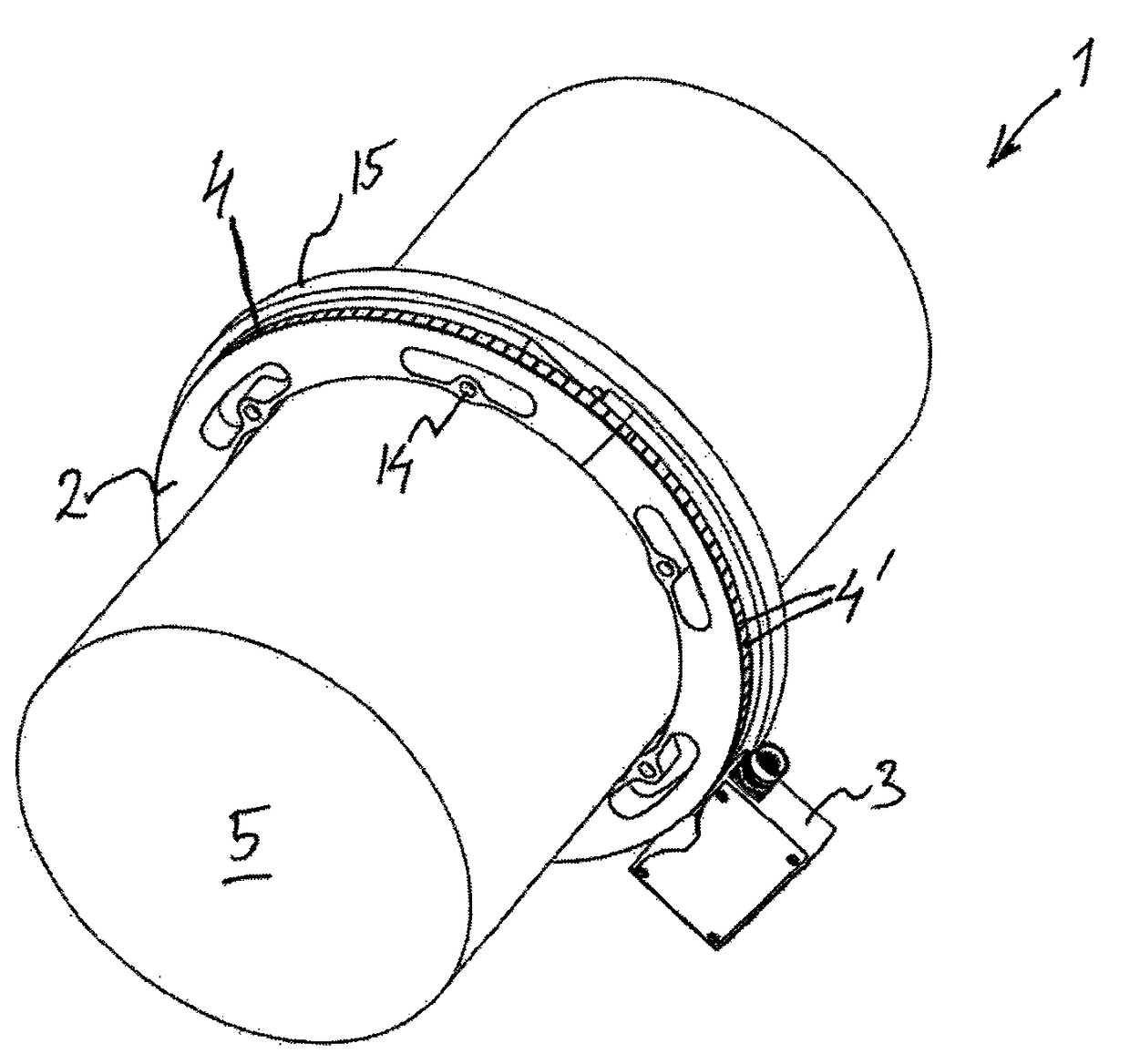
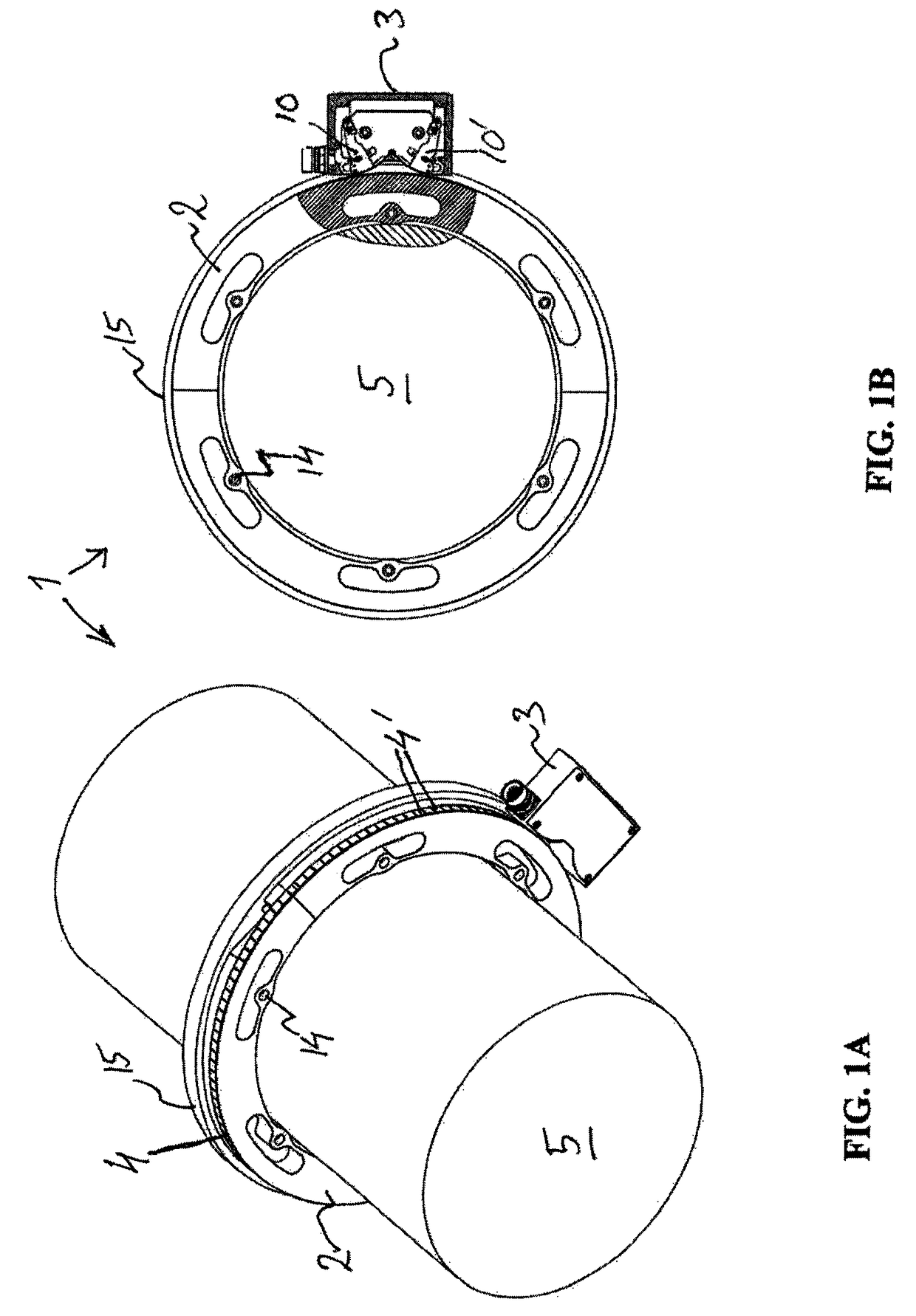
[0024]FIGS. 1A, 1B, and 2 schematically illustrate an encoder assembly 1 according to an example embodiment of the present invention. The encoder 1 is suitable for magnetic, magnetoresistive, optical / reflective, or inductive scanning and includes a sensor head 3, for scanning a rotatable encoding member 4, such as directed towards a shaft 5 (see FIG. 2) of a machine having an encoding member or towards a carrier ring 4 (see FIGS. 1A and 1B), with the encoding member, mounted on the shaft 5. Hence, the encoding member is caused to rotate as the shaft rotates, and the sensor head 1 is firmly affixed to a casing of the machine. For instance, in a magnetic encoder, the encoding member 4 includes magnetic element(s), such as a magnetic tape with magnetic poles 4′, carried directly on the shaft 5 or on a carrier ring 4. The magnetic element(s) may also include, e.g., one or more magnets that are attached in plastics and molded onto a ring where it is magnetized. At least two detectors in ...


PUM


Abstract

A sensor head for an encoder assembly includes a housing and at least two detectors. The sensor head is intended for scanning directly toward a rotatable encoding member positioned on a carrier ring. The carrier ring is intended to be installed on a shaft of a machine. The detectors are arranged on detector strips are displaceably attached to the housing.

Description

CROSS-REFERENCE TO RELATED APPLICATIONS[0001]The present application claims priority to Application No. 1250455-1, filed in the Kingdom of Sweden on May 4, 2012, which is expressly incorporated herein in its entirety by reference thereto.FIELD OF THE INVENTION[0002]The present invention relates to a sensor head for an encoder.BACKGROUND INFORMATION[0003]Encoders are often used in environments where they are subjected to significant vibrations, and often in a heavily contaminated environment. The encoder may, for instance, be used to generate the position values of shaft rotation in a machine. For instance, the encoder may be attached to a rotating shaft in the machine. The encoding disk is caused to rotate as the shaft rotates, and the encoder casing and detector are firmly affixed to the casing of the machine.[0004]In certain conventional systems, an optoelectrical state encoder is used, which includes an encoding disk that has an optically readable pattern. The disk pattern is rea...

Claims


Application Information

Patent Timeline
Patent Type & Authority Patents(United States)
IPC IPC(8): G01R33/00G01B7/14G01D5/347
CPCG01B7/14G01D5/34715G01D11/245G01P1/026G01P3/487
Inventor ARNSTEIN, RICHARDLARSSON, MAGNUS
Owner LEINE & LINDE
Why Eureka
Try Eureka