
Method and bearing for supporting rotatable devices, particularly a medical scanner

a technology for supporting rotatable devices and bearings, which is applied in the field of bearings supporting rotatable devices, can solve the problems of frequently insufficient measures to keep the noise level of bearings at an adequate level, and achieve the effect of further reducing nois

Active Publication Date: 2012-11-27
ROTHE ERDE GMBH +1
View PDF16 Cites 6 Cited by
  • Summary
  • Abstract
  • Description
  • Claims
  • Application Information

AI Technical Summary

Benefits of technology

The present invention provides a method and bearing for reducing noise emission in devices. The bearing uses large-size anti-friction bearings with electromagnets to prevent structure-borne noise. The electromagnets are distributed over the bearing in both axial and radial directions to support the bearing forces and moments. The bearing also contains optical or inductive distance sensors to measure the gap distance between the outer and inner rings and maintain it constant. The electromagnets can be controlled to vary the stiffness of the bearing and avoid vibrations. The bearing can also be used for balancing during commissioning or to compensate for imbalances during running operation. The invention provides a solution for reducing noise in devices and improving their performance.

Problems solved by technology

With high peripheral speeds, however, those measures described herein above are frequently insufficient to keep the noise level of the bearing at an adequately low level.

Method used


Image

  • Method and bearing for supporting rotatable devices, particularly a medical scanner
  • Method and bearing for supporting rotatable devices, particularly a medical scanner
  • Method and bearing for supporting rotatable devices, particularly a medical scanner

Examples


Embodiment Construction

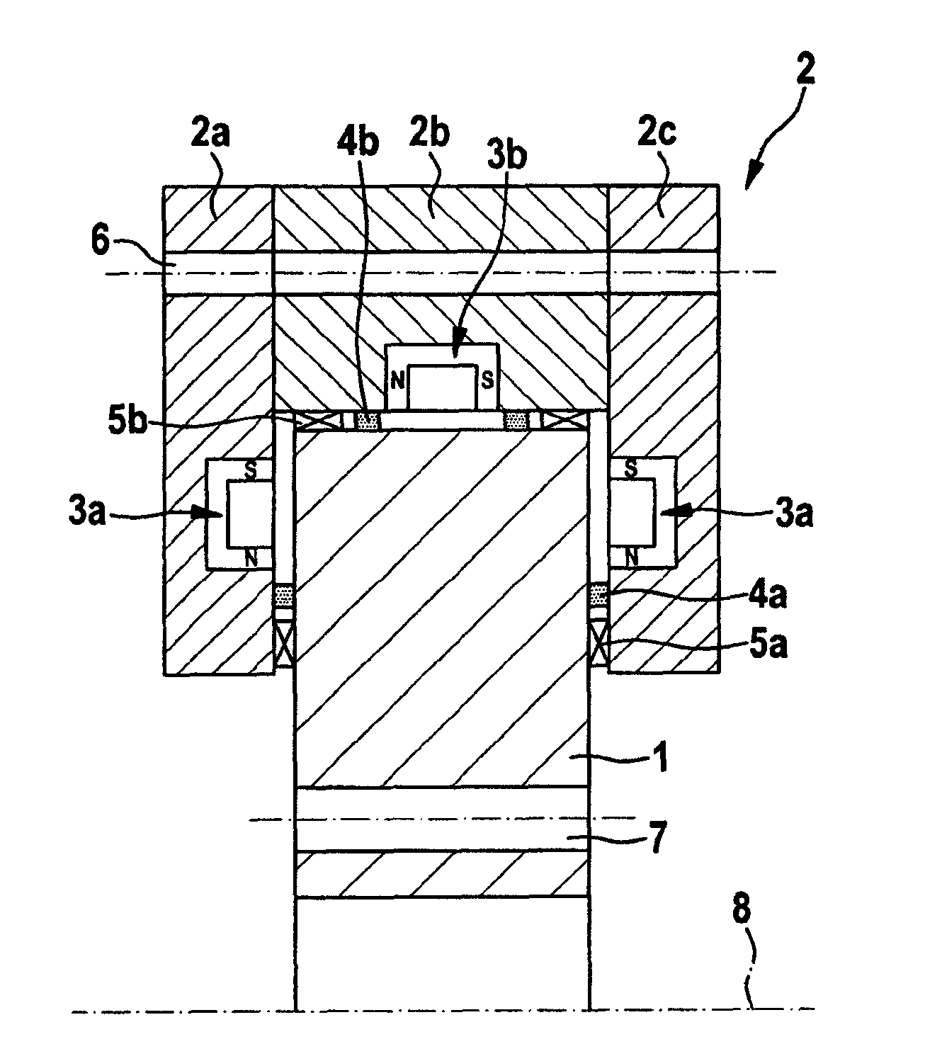
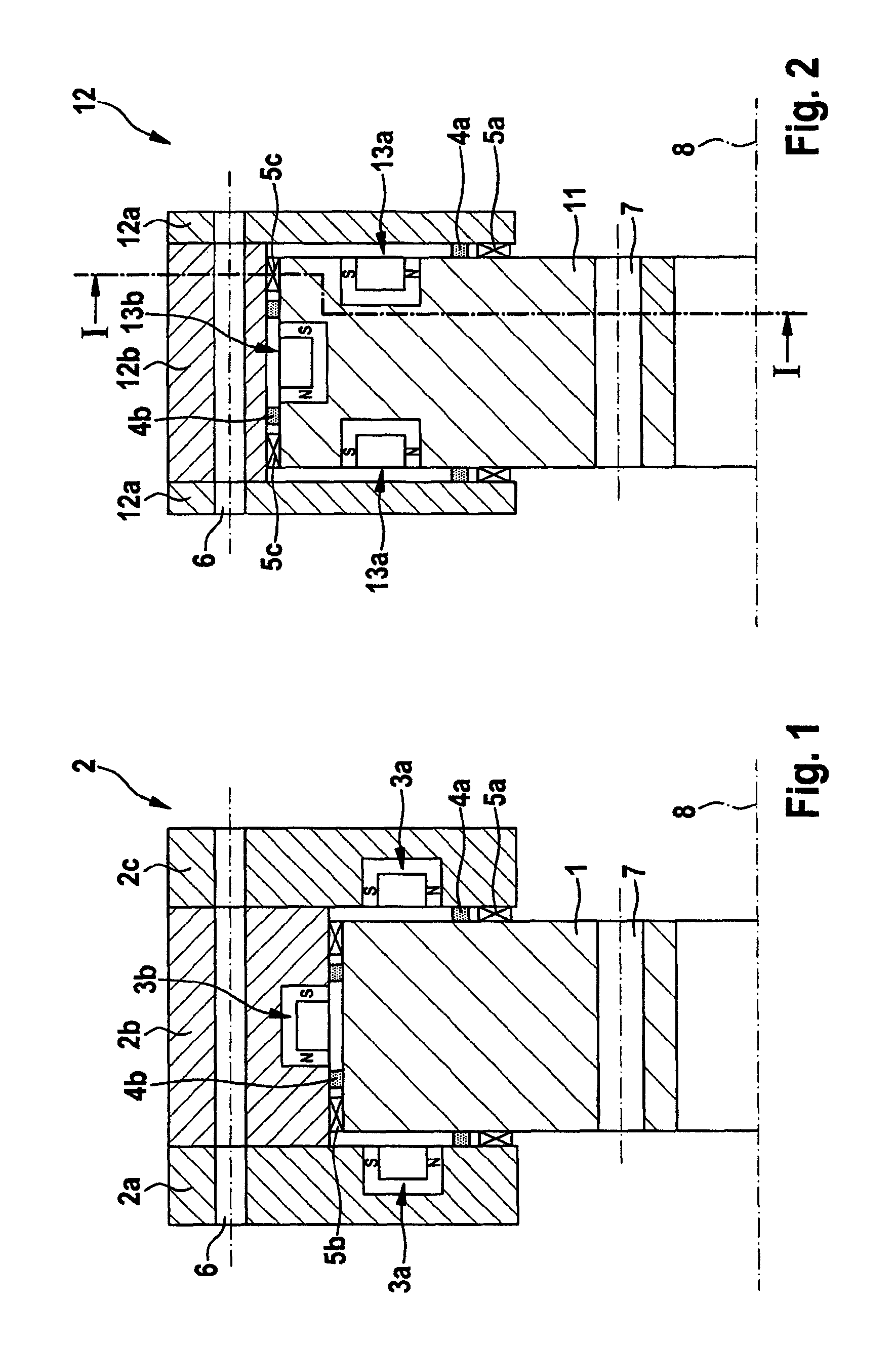
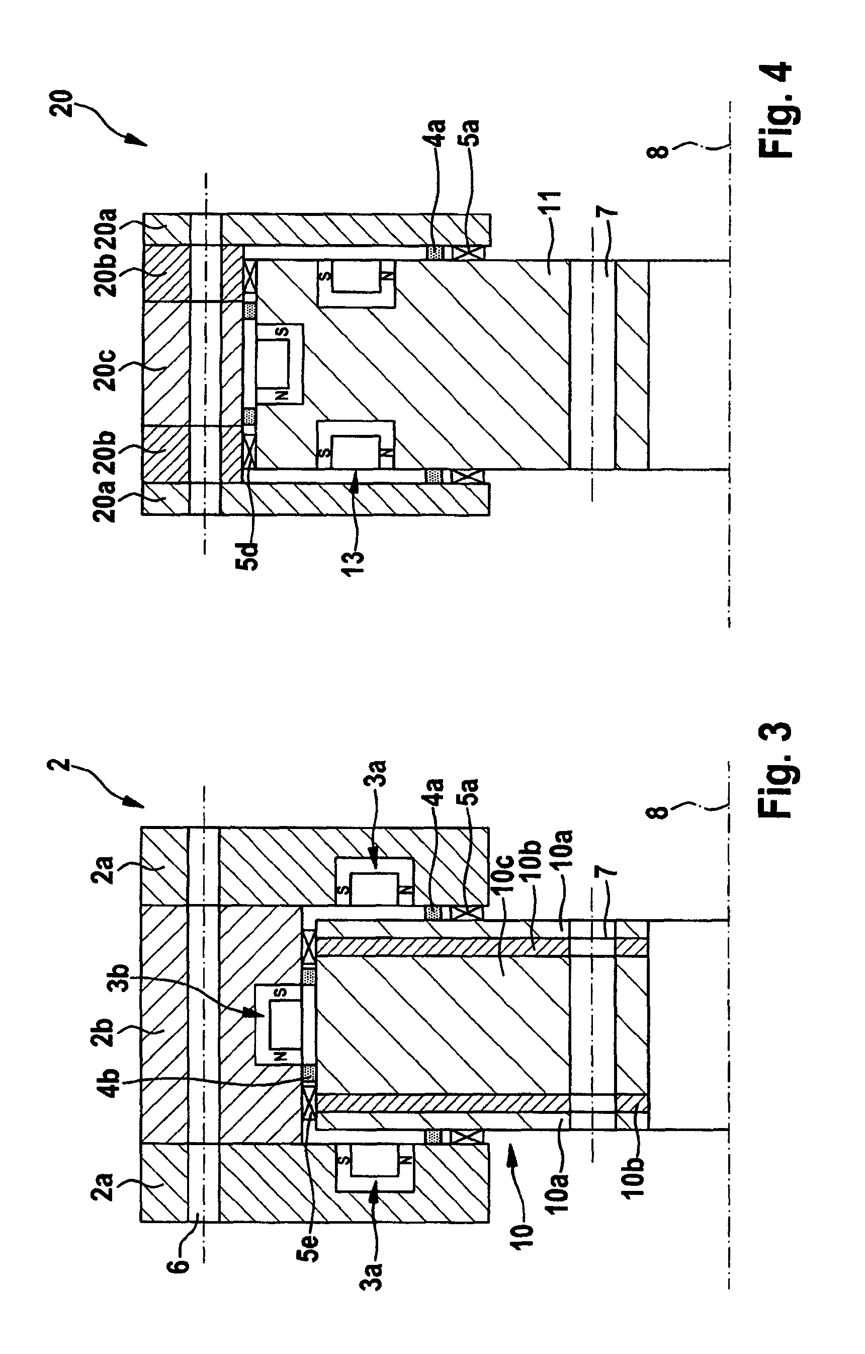
[0019]Referring to the drawings in particular, according to FIG. 1, an outer ring 2 is configured as a stator, with electromagnets 3a being disposed in the individual outer rings 2a and 2c and with the electromagnets 3b being disposed in the outer ring 2b which lie opposite to the two axial surfaces and to the radial surface of the inner ring 1 serving as rotor. By the aid of these electromagnets 3a, 3b, the inner ring 1 and the outer ring 2 are kept at an even distance to each other during the rotation about the common rotating axis B so that there is no metallic contact between both bearing rings on operation. To monitor and control the gap distance, distance sensors 4a, 4b are provided near the electromagnets 3a, 3b. The arrest bearings 5a-5e are fastened either to the outer ring 2, 12, 20 or to the inner ring 1, 10, 11 and in normal operation they have a small distance towards the opposite area. On failure of the electric power supply to electromagnets 3a, 3b, these arrest beari...


PUM


Abstract

A method is provided for supporting rotatable devices, particularly a medical scanner having an inner ring and an outer ring. According to the invention, the inner ring and outer ring are guided without contact in the axial and / or radial direction by the magnetic field of electromagnets, and the distance between them is monitored and controlled by means of distance sensors. For a bearing implementing said method according to the invention, the outer ring is made in multiple parts and has a U-shaped cross section that is open to the inside in the assembled state, into which the inner ring (1, 10, 11) extends, and electromagnets and distance sensors are disposed in the axially and radially opposite areas of the inner ring or outer ring.

Description

CROSS REFERENCE TO RELATED APPLICATIONS[0001]This application is a United States National Phase application of International Application PCT / EP2008 / 006644 and claims the benefit of priority under 35 U.S.C. §119 of German Patent DE 10 2007 038 489.2 filed Aug. 14, 2007, the entire contents of which are incorporated herein by reference.FIELD OF THE INVENTION[0002]The present invention relates to a method for bearing rotatable devices, particularly a medical scanner, comprised of at least one inner ring and at least one outer ring, and to a bearing particularly for implementing said method.BACKGROUND OF THE INVENTION[0003]Noise emission represents a significant design criterion, particularly for medical scanners. An important noise source on operating a scanner is the anti-friction bearing which continually generates structure-borne noise by a permanent rotation (rolling contact) of the rolling bodies and transfers it to the connected structures which emit it as air-borne noise.[0004]T...

Claims


Application Information

Patent Timeline
Patent Type & Authority Patents(United States)
IPC IPC(8): H02K7/09
CPCF16C32/0493F16C33/38F16C39/02F16C2300/14F16C2316/10F16C32/0442
Inventor BREUCKER, UWE-OTTOCLAUS, WOLFGANGROLLMANN, JORGLOSER, FREIDRICHZHENG, QINGHUABAUER, MARKUS
Owner ROTHE ERDE GMBH
Learn More