Gear shifting mechanism with a locking mechanism for a gear shift transmission

a gear shift transmission and locking mechanism technology, applied in the direction of mechanical control devices, process and machine control, instruments, etc., to achieve the effect of simplifying the structure of the gear shifting mechanism and less expensive structur

Active Publication Date: 2012-12-04
GETRAG FORD TRANSMISSIONS GMBH
View PDF14 Cites 8 Cited by
  • Summary
  • Abstract
  • Description
  • Claims
  • Application Information

AI Technical Summary

Benefits of technology

[0008]It is therefore an object of the invention to create a gear shifting mechanism for a gear shift transmission comprising a plurality of gears that has a simple structure and prevents that two gears of the gear shift transmission are unintentionally engaged at the same time.
[0010]The gear shifting mechanism according to the invention has the characteristics that the contact face of the locking element and the locking face of the first gear shift fork are designed such that in a locking position a force for moving the first gear shift fork out of its neutral position does not generate a resulting component of the force that forces the locking element against of the second gear shift fork. Preferably, a support block bears the forces the locking element is subjected to when moving the first gear shift fork out of its neutral position. Due to the preferred bearing of the entire forces by means of the support block, the first locking element does not transmit any forces onto the second gear shift fork so that a support of the second gear shift fork does not have to be designed for bearing such forces. This simplifies the structure of the gear shifting mechanism and allows for a less expensive structure.
[0011]The locking mechanism accomplishes that the first gear shift fork and the second gear shift fork do not assume unintentionally at the same time an engaged position and therefore prevents that two gears of a gear shift transmission having multiple gears are engaged simultaneously. The gear shift mechanism according to the present invention can also be used in a dual clutch transmission having two partial transmissions. For providing an acceleration performance without any interruption in the driving power one gear each is engaged in each partial transmission of the dual clutch transmission. In this case, the control provides for engaging gears in a dual clutch transmission simultaneously. However, with respect to a partial transmission, it has to be taken care of only engaging one gear at any given point in time within that partial transmission. Therefore, when using of the gear shifting mechanism according to the invention in a dual clutch transmission, the locking action of the locking mechanism relates to one of the partial transmissions, respectively. This does of course not exclude that for each partial transmission of a dual clutch transmission one gear shifting mechanism according to the present invention is provided, respectively.DETAILED DESCRIPTION OF THE INVENTION
[0013]The locking element may be designed as a locking pin engaging with its one end a recess provided in the first gear shift fork, wherein an inner wall forming of the boundaries of the recess provides the locking face. For example, the recess may be a slot having a substantially rectangular cross section and comprise two side walls and a bottom of the slot. The side walls opposing each other form the respective locking faces. If the locking pin engages the slot, the gear shift fork is locked in two directions. This prevents securely an unintentional movement of a gear shift fork from the neutral position into two directions.
[0019]In an alternative, the locking mechanism may comprise a second locking element that assumes a locking position fixed by the first gear shift fork when it engages a gear, wherein in this locking position a contact face of the second locking element and a locking face of the second gear shift fork engage each other and therefore hold the second gear shift fork in its neutral position, wherein the contact face of the second locking element and the locking face of the second gear shift fork are designed such that in this locking position a force for moving the second gear shift fork out of its neutral position does not generate a resulting component of force that would force the second locking element against the first gear shift fork. According to this embodiment, one locking element each is provided for locking a respective gear shift fork in its neutral position. While the first locking element accomplishes locking of the first gear shift fork, the second locking element is responsible for locking the second gear shift fork in its neutral position. This requires, however, two independent locking elements, but due to their functions and directed to one gear shift fork only each, these locking elements can be designed and supported in a simple manner. The use of two locking elements accomplishes also in a simple manner that the control face and the locking face are separated from each other and can therefore be designed independently (for example with respect to tolerances).

Problems solved by technology

However, with respect to a partial transmission, it has to be taken care of only engaging one gear at any given point in time within that partial transmission.

Method used


Image

  • Gear shifting mechanism with a locking mechanism for a gear shift transmission
  • Gear shifting mechanism with a locking mechanism for a gear shift transmission
  • Gear shifting mechanism with a locking mechanism for a gear shift transmission

Examples


first embodiment

[0025]FIG. 2 schematically parts of the invention in the variety of positions;

[0026]FIG. 3 a leg spring according to the embodiment shown in FIG. 2;

[0027]FIG. 4 a locking element according to the embodiment shown in FIG. 2; and

second embodiment

[0028]FIG. 5 schematically parts of the invention.

DETAILED DESCRIPTION OF THE DRAWINGS

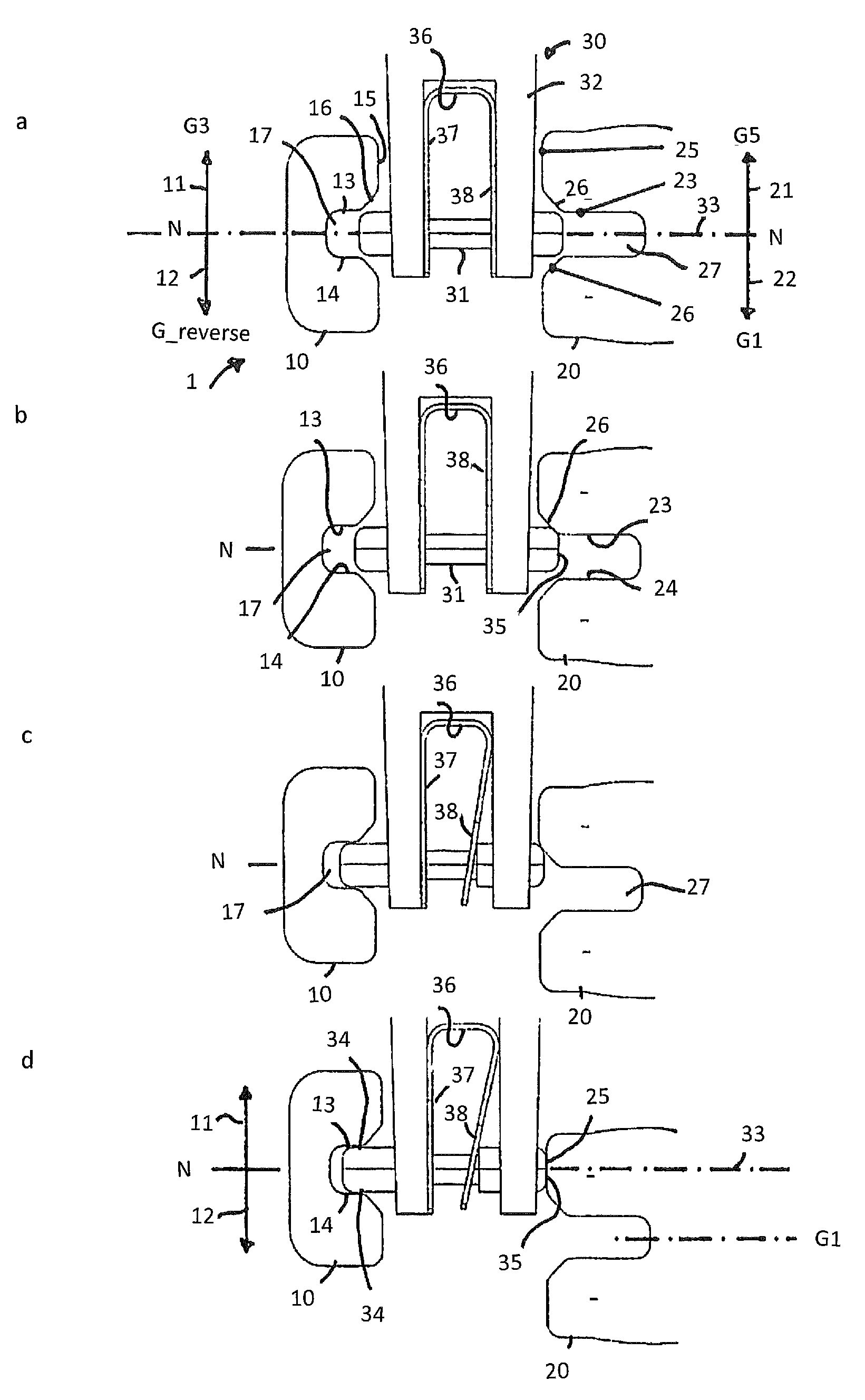
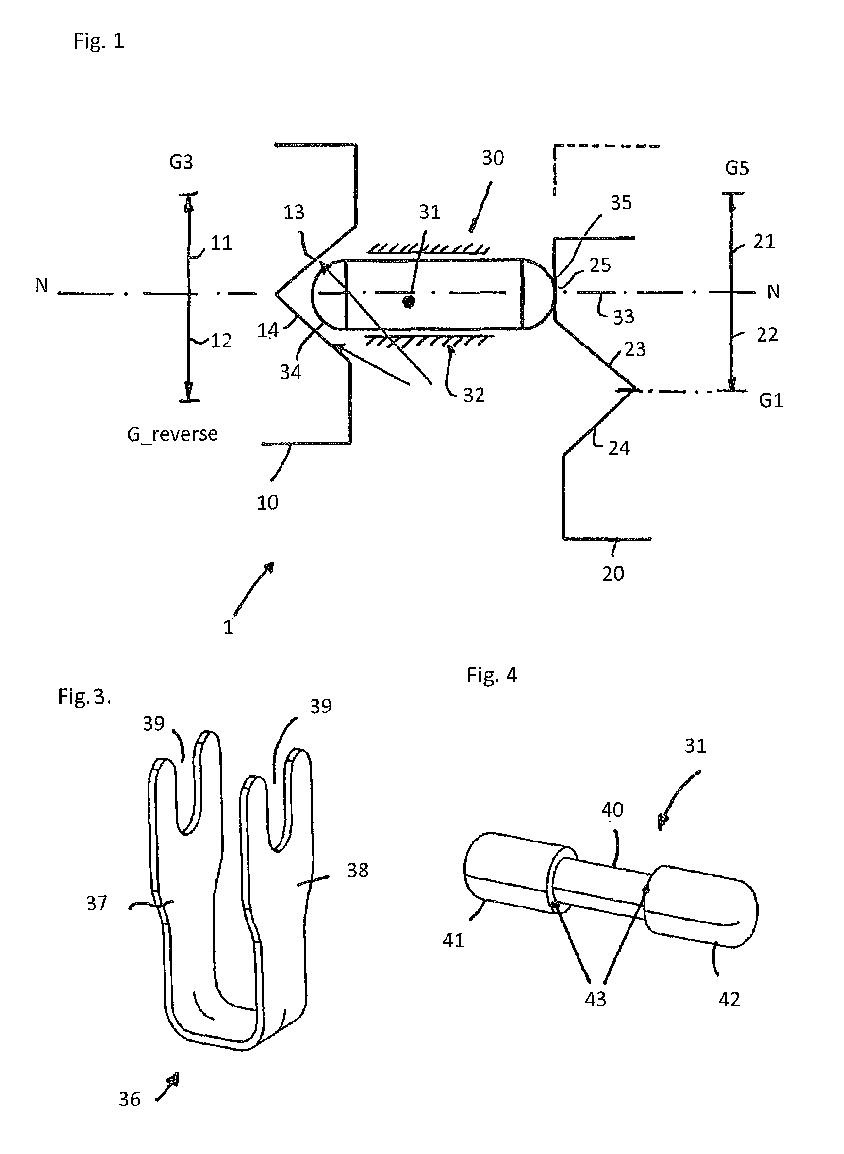
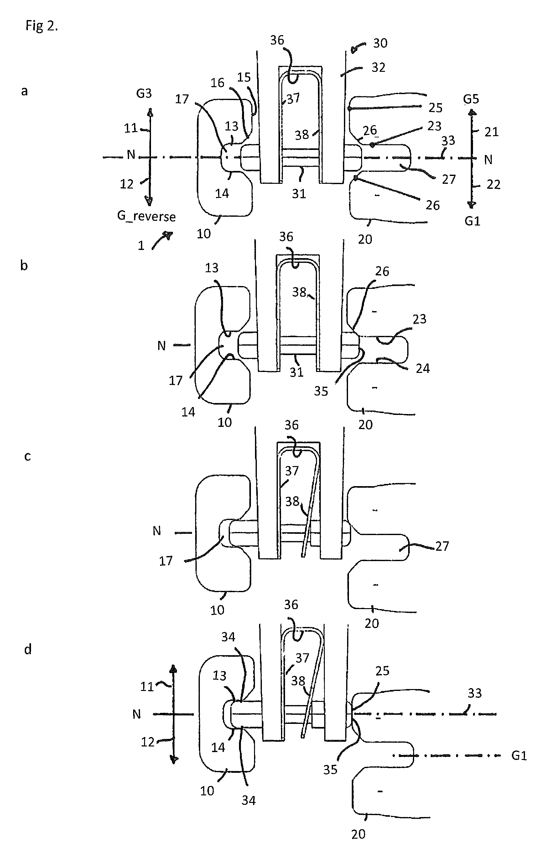
[0029]FIG. 1 shows schematically parts of a shifting mechanism according to the prior art. A first gear shift fork 10 that is only shown in part can be moved from the neutral position N in direction of arrows 11, 12.

[0030]Next to the first gear shift fork 10, a second gear shift fork 20 (only shown in part) is provided that can be moved in parallel to the first gear shift fork 10 in direction of the arrows 21, 22. In a gear shift transmission having multiple gears and having the gear shift mechanism installed, the gear shift forks 10, 20 can be allocated to two gears each. In particular, the gear shift transmission having multiple gears can be a partial transmission of a dual clutch transmission, accommodating the odd numbered forward gears G1, G3, G5 and one reverse gear G_reverse. The second gear shift fork 20 is shown in a gear engaged gear position where the forward gear G1 is engaged. The othe...


PUM


Abstract

A gear shift mechanism of a gear shift transmission having a plurality of gears is described. A first movable gear shift fork and at least one second movable gear shift fork are provided for engaging gears of the gear shift transmission and assuming a neutral position as well as an engaged position where a gear allocated to a respective one of the first and second gear shift forks is engaged. A locking mechanism comprising a locking element is provided that prevents that both gear shift forks can assume at the same time unintentionally an engaged position. The locking mechanism is designed such that in a locking position a force for moving the first gear shift fork out of its neutral position does not generate a resulting component of force that would force the locking element against the second gear shift fork.

Description

CROSS REFERENCE TO RELATED APPLICATION[0001]This application claims the priority right from the German patent application DE 102008050810.1 that was filed on Oct. 8, 2008, the content of which is herewith incorporated in its entirety by reference.BACKGROUND OF THE INVENTION[0002]The invention comprises a gear shifting mechanism for a gear shift transmission comprising a plurality of gears, the gear shifting mechanism comprising a first movable gear shift fork and at least one second movable gear shift fork adapted to engage gears and a locking mechanism preventing that the gear shift forks can assume at the same time unintentionally an engaged position.[0003]From EP 0 331 278 A2 a gear shifting mechanism for a gear shift transmission comprising a plurality of gears is known wherein a first gear shift fork and a second gear shift fork are provided. Each of the gear shift forks comprises a gear shift rod, the gear shift rods extending in parallel to each other. The gear shift forks ca...

Claims


Application Information

Patent Timeline
Patent Type & Authority Patents(United States)
IPC IPC(8): G05G5/08B60K20/02
CPCF16H63/36Y10T74/20104Y10T74/2011Y10T74/20116Y10T74/20128
Inventor DOELLING, MATTHIASHEGERATH, ANDREASSOEHNGE, PATRICK
Owner GETRAG FORD TRANSMISSIONS GMBH
Why Eureka
Try Eureka