Implantable adjustable valve

a technology of adjustable valves and valves, which is applied in the direction of valve operating means/releasing devices, functional valve types, wound drains, etc., can solve the problems of inconvenient use, and inability to adjust the valve, etc., to achieve the effect of improving the resistance of the valve to unintentional setting changes, and improving the safety of patients

Active Publication Date: 2012-12-04
INTEGRA LIFESCI SWITZERLAND SARL
View PDF53 Cites 58 Cited by
  • Summary
  • Abstract
  • Description
  • Claims
  • Application Information

AI Technical Summary

Benefits of technology

[0008]An object of the present invention is to provide an improved implantable adjustable valve unit which resists unintentional performance setting changes when the unit is subjected to vibration, jarring or unintended magnetic fields.
[0009]Another object of the present invention is to provide such a valve unit which readily allows desired non-invasive changes to its pressure or flow control settings.
[0011]This invention features a valve unit capable of being implanted in a patient and having adjustable performance settings to regulate passage of a bodily fluid. The valve unit includes a casing defining a port, such as an inlet or an outlet for the bodily fluid, and a valve mechanism positioned at the port. The valve mechanism includes a movable valve member. The valve unit further includes a rotor disposed at a first location in the casing and having an axle which turns about an axis of rotation. The rotor defines a plurality of radially flat cam surfaces, each cam surface occupying an arc about the axis of rotation. A spring arm unit, disposed at a second location in the casing, has a cam follower arm in slidable contact with the cam surfaces of the rotor and has a resilient spring element applying a closing effect with the valve member at the port to establish a performance setting for the valve unit. Sufficient rotation of the rotor to change the cam surface in contact with the cam follower alters the closing effect with which the valve member moves relative to the port and thereby alters the performance setting of the valve unit.
[0020]In yet other embodiments, a rotor retention spring biases the rotor to the constrained condition. The movable valve member is a ball and the valve mechanism includes a seat for the ball that is adjustable within the port during assembly of the valve unit to calibrate the pressure settings. The spring arm unit further includes a stiffener arm and at least the outermost cam surface enables the stiffener arm to be forced against the spring element to shorten its effective length and thereby increase its closing force against the movable valve member.

Problems solved by technology

The excessive build-up of cerebrospinal fluid compresses brain tissues, which eventually leads to brain damage.
To differing degrees, these valves are not optimal regarding resistance to unintentional setting changes, ease of use in achieving the desired valve setting, and detection of actual valve setting.
As recognized by McCusker et al. in U.S. Pat. No. 7,390,310, for example, such strong magnetic fields can interfere with implanted devices including shunt valves.

Method used


Image

  • Implantable adjustable valve
  • Implantable adjustable valve
  • Implantable adjustable valve

Examples


Embodiment Construction

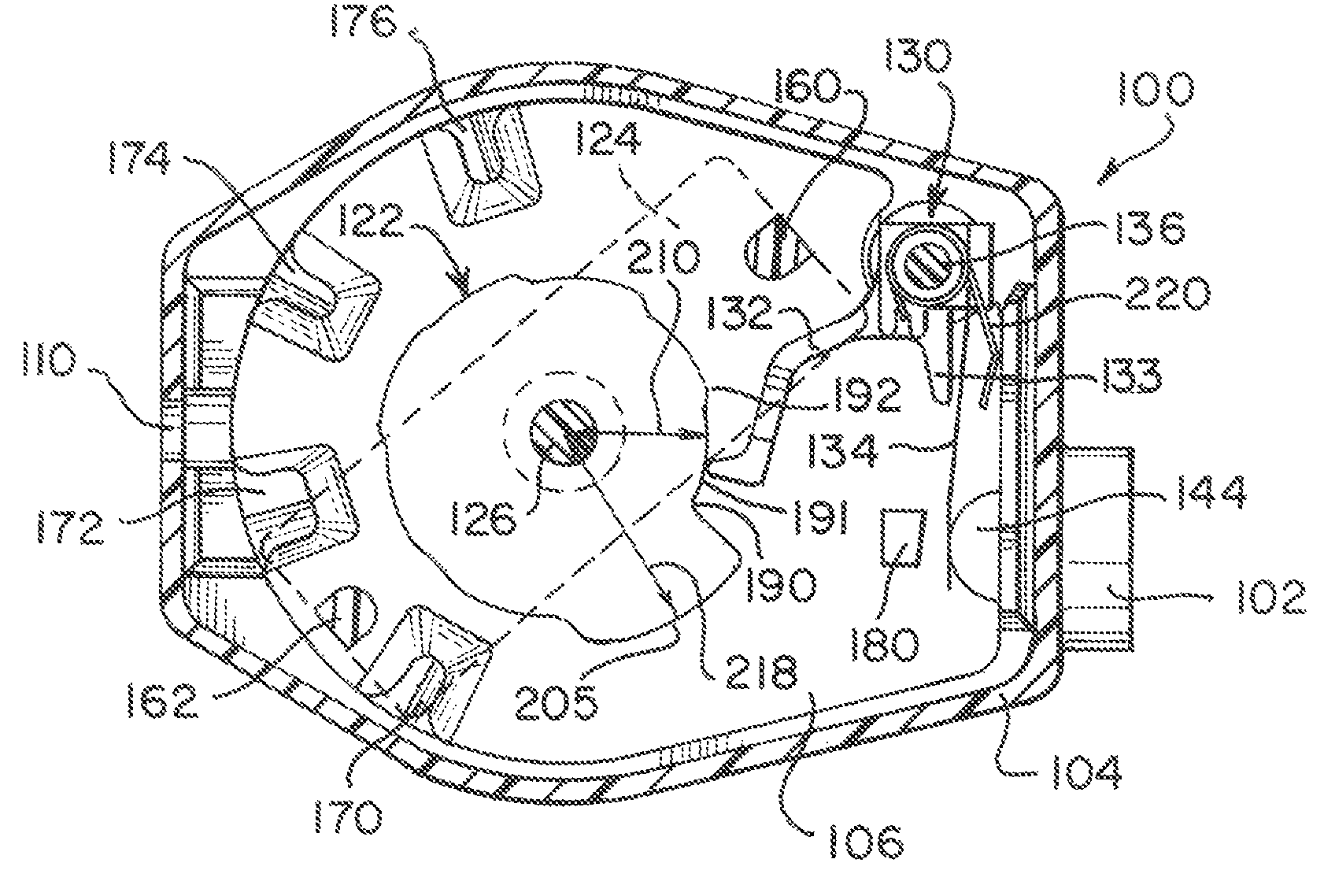
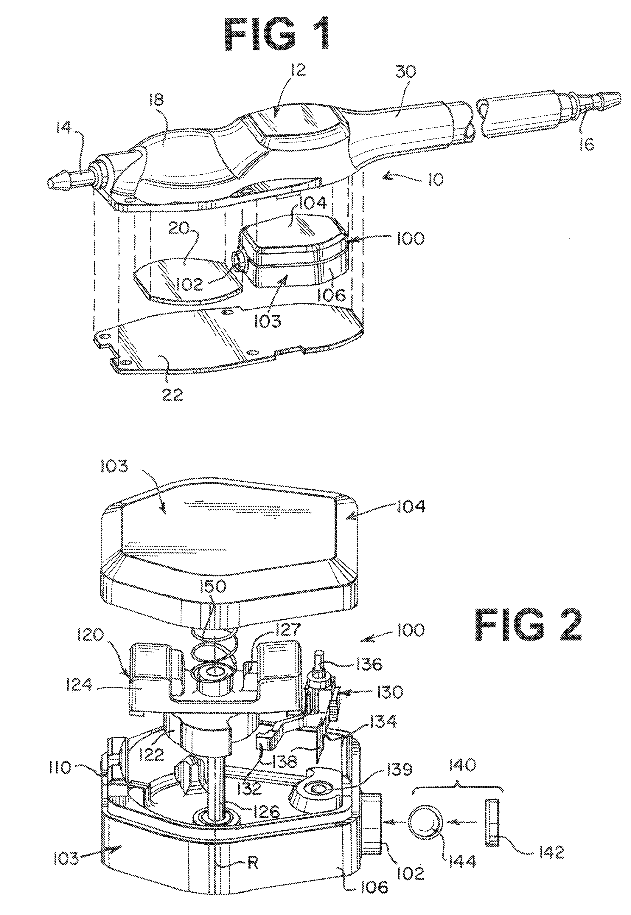
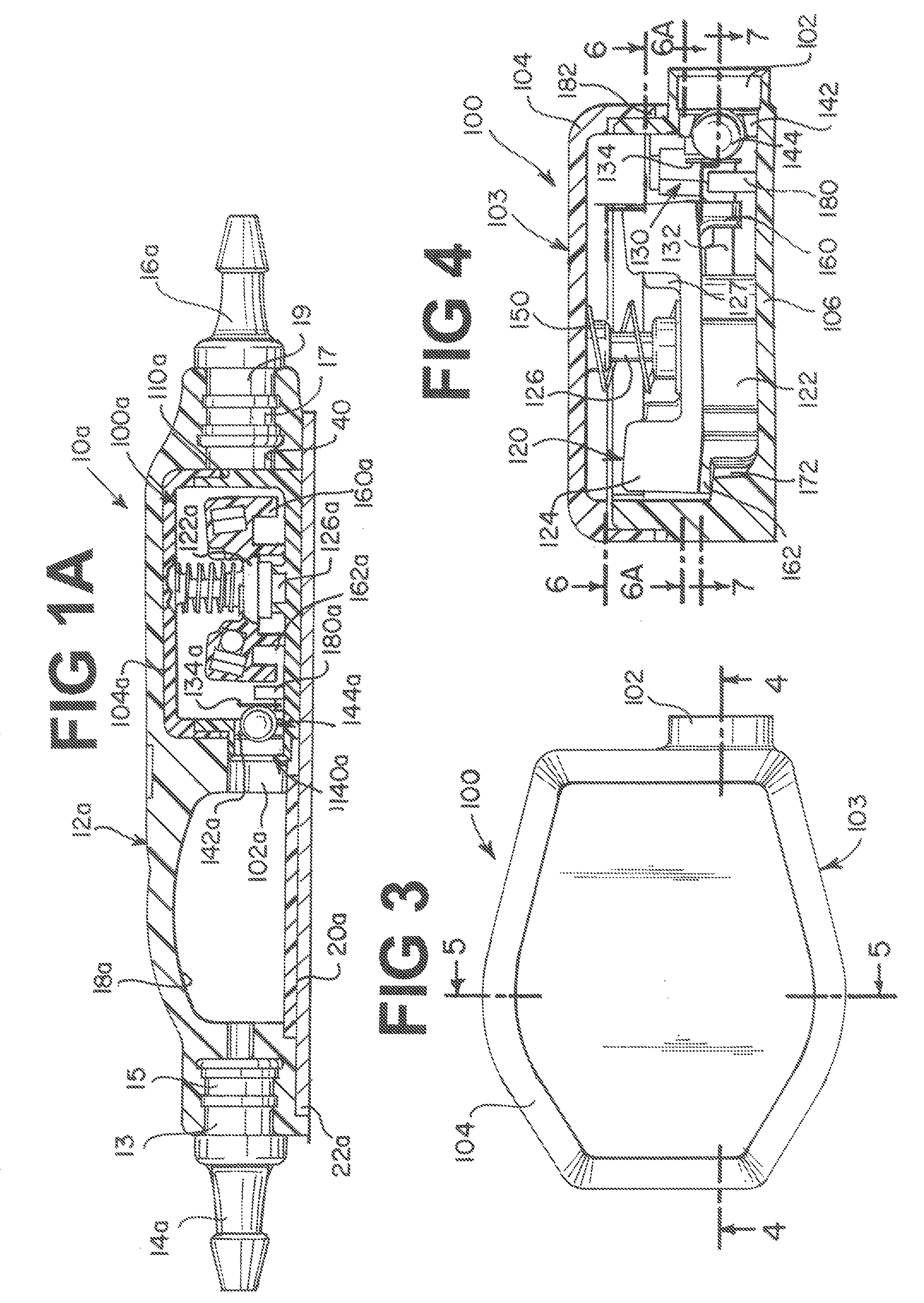
[0062]One construction of an adjustable valve unit according to the present invention has a rotor disposed at a first location in a casing. The rotor defines a plurality of arcuate, radially flat cam surfaces. Each cam surface occupies an arc about the axis of rotation of the rotor. A spring arm unit disposed at a second location in the casing has a substantially rigid cam follower arm in slidable contact with the arcuate cam surfaces of the rotor and has a resilient spring element applying a closing effect, such as a closing force, to a movable valve member, such as a ball, against a seat to establish a pressure setting for the valve unit. Other performance settings such as flow control are achieved in other constructions, such as described in relation to FIGS. 28 and 29 below. Preferably, the radially flat cam surfaces are positioned about the rotor in a successive arrangement such that a radial distance from the axis of rotation for each successive cam surface is larger than the ...


PUM


Abstract

A valve unit capable of being implanted in a patient and having adjustable performance settings, such as pressure settings and / or flow control, to regulate passage of a bodily fluid. A casing defines a port for the bodily fluid, and a valve mechanism positioned at the port includes a movable valve member. The valve unit further includes a rotor disposed at a first location in the casing and having an axle which turns about an axis of rotation. The rotor defines a plurality of arcuate, radially flat cam surfaces. Each cam surface occupies an arc about the axis of rotation. A spring arm unit is disposed at a second location in the casing having a cam follower arm in slidable contact with the cam surfaces of the rotor and having a resilient spring element applying a closing effect with the movable valve member to establish a performance setting for the valve unit. Sufficient rotation of the rotor to change the cam surface in contact with the cam follower alters the closing effect with which the valve member moves relative to the port and thereby alters the performance setting of the valve unit.

Description

BACKGROUND OF THE INVENTION[0001]1. Field of the Invention[0002]The invention relates to valves for implantable medical devices and more particularly to adjustable valve mechanisms which resist unintentional performance setting changes.[0003]2. Description of the Related Art[0004]There are a number of treatments for medical conditions which require fluid to be removed from an organ or tissue of a patient. One such condition is hydrocephalus, where cerebrospinal fluid abnormally accumulates in the skull faster than it is withdrawn by the body. The excessive build-up of cerebrospinal fluid compresses brain tissues, which eventually leads to brain damage.[0005]Hydrocephalus is commonly treated by implanting a shunt in fluid communication with a ventricle within the brain to withdraw cerebrospinal fluid at a desired rate. Typically, the rate of withdrawal of cerebrospinal fluid is controlled by a valve having different pressure settings which a clinician adjusts pre-operatively. A numbe...

Claims


Application Information

Patent Timeline
Patent Type & Authority Patents(United States)
IPC IPC(8): A61M5/00
CPCA61M27/006F16K15/046F16K31/088F16K15/183F16K37/0058F16K31/52425F16K35/16F16K15/1823Y10T137/7906Y10T137/8242
Inventor WILSON, STEPHEN F.DEFUSCO, MICHAEL
Owner INTEGRA LIFESCI SWITZERLAND SARL
Why Eureka
Try Eureka