Magneto-rheological dampers for semi-active suspension systems

a semi-active suspension and damper technology, applied in the field of hydrostatic dampers, can solve the problems of short-lived seals used in containing magneto-rheological fluid within the damper body as the piston rod reciprocates within the damper body

Active Publication Date: 2012-12-04
LORD CORP
View PDF47 Cites 28 Cited by
  • Summary
  • Abstract
  • Description
  • Claims
  • Application Information

AI Technical Summary

Problems solved by technology

However, at such high charge pressures, seals used in containing magneto-rheological fluid within the damper body as the piston rod reciprocates within the damper body are likely to be short-lived.

Method used


Image

  • Magneto-rheological dampers for semi-active suspension systems
  • Magneto-rheological dampers for semi-active suspension systems
  • Magneto-rheological dampers for semi-active suspension systems

Examples


Embodiment Construction

[0015]The invention will now be described in detail with reference to a few preferred embodiments, as illustrated in the accompanying drawings. In describing the preferred embodiments, numerous specific details are set forth in order to provide a thorough understanding of the invention. However, it will be apparent to one skilled in the art that the invention may be practiced without some or all of these specific details. In other instances, well-known features and / or process steps have not been described in detail so as not to unnecessarily obscure the invention. In addition, like or identical reference numerals are used to identify common or similar elements.

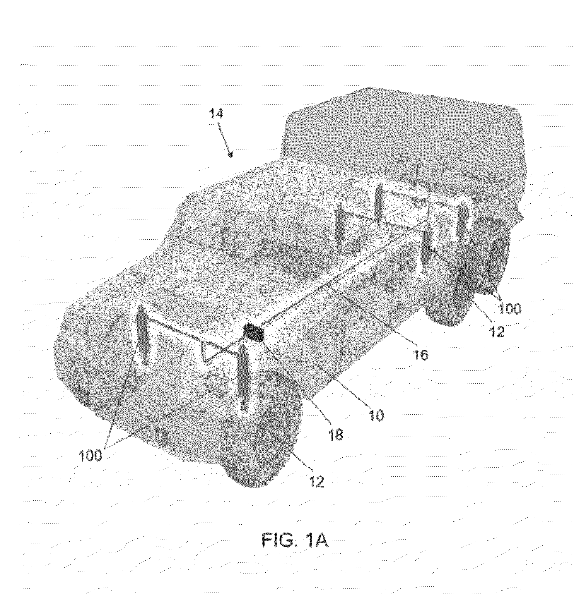
[0016]FIG. 1A depicts an exemplary vehicle 14 with magneto-rheological fluid dampers 100 according to the invention connected between the body 10 and the wheels 12 of the vehicle. The magneto-rheological fluid dampers 100 are in communication with a suspension control system 16 including a control unit 18. The vehicle 14 in pr...


PUM


Abstract

A magneto-rheological fluid damper includes a damper body having a reservoir for a magneto-rheological fluid, a piston rod, a piston rod guide disposed within the damper body, where the piston rod guide has a passage therein for receiving the piston rod. The magneto-rheological fluid damper further includes at least a first piston rod seal and at least a second piston rod seal arranged to seal between the piston rod guide and the piston rod. The magneto-rheological fluid damper further includes a fluid chamber defined between the piston rod guide and the piston rod, the fluid chamber being in communication with the reservoir. The magneto-rheological fluid damper further includes a piston rod guide filter arranged in a communication path between the fluid chamber and the reservoir to filter particulates out of the magneto-rheological fluid entering the fluid chamber. The magneto-rheological fluid damper further includes an accumulator arranged between the piston rod guide and the damper body.

Description

CROSS REFERENCE[0001]This application is a continuation-in-part of application Ser. No. 11 / 742,911, filed May 1, 2007 now U.S. Pat. No. 7,849,983, which claims the benefit of U.S. Provisional Application No. 60 / 796,567, filed May 1, 2006, all of which the benefit are claimed and are herein incorporated by reference. This application is a continuation-in-part of International Application No. PCT / US07 / 83171, filed Oct. 31, 2007, which claims the benefit of application Ser. No. 11 / 742,911, filed May 1, 2007, which claims the benefit of U.S. Provisional Application No. 60 / 796,567, filed May 1, 2006, all of which the benefit are claimed and are herein incorporated by reference.FIELD OF THE INVENTION[0002]The invention relates generally to the field of hydraulic dampers. More particularly, the invention relates to the field of magneto-rheological dampers.BACKGROUND OF THE INVENTION[0003]Magneto-rheological fluid dampers typically include a damper body with a sliding piston rod received th...

Claims


Application Information

Patent Timeline
Patent Type & Authority Patents(United States)
IPC IPC(8): F16F15/03
CPCB60G99/002B60G99/008F16F9/064F16F9/535F16F13/002B60G2300/07B60G2600/184
Inventor MARJORAM, ROBERT H.HILDEBRAND, STEPHEN F.IVERS, DOUGLAS E.ERICKSEN, GREGORYMCMAHON, WILLIAM J.ST. CLAIR, KENNETH A.
Owner LORD CORP
Why Eureka
Try Eureka