Integration of a semi-active laser seeker into the dsu-33 proximity sensor

a laser seeker and proximity sensor technology, applied in the field of proximity sensors, can solve the problems of bias and drift errors, inability to easily use moving targets, and inherent registration of gps coordinate based systems,

Inactive Publication Date: 2005-02-10
NORTHROP GRUMMAN SYST CORP
View PDF13 Cites 41 Cited by
  • Summary
  • Abstract
  • Description
  • Claims
  • Application Information

AI Technical Summary

Benefits of technology

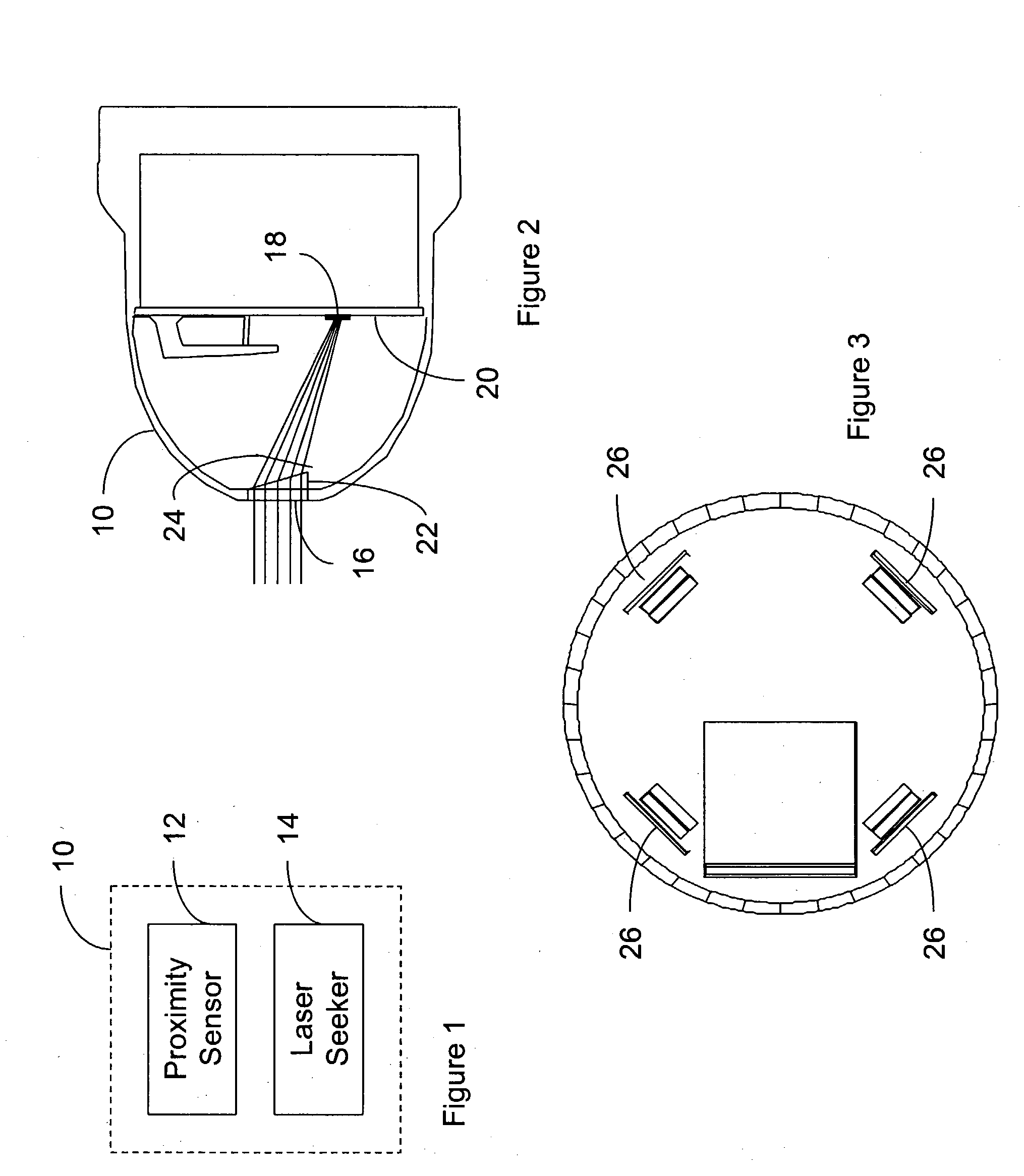
[0017] Applicant's have also invented an improved proximity sensor which utilizes an unfocused laser radiation sensor system attached to the proximity sensor which is configured and arranged to detect laser radiation reflected from a target which passes through the radome and output the azimuth and elevation angles to the target to the guidance system. The unfocused laser radiation sensor system is further comprised of a plurality of optical detectors arranged around a longitudinal axis of the proximity sensor, each optical detector on receiving incoming optical energy producing an optical detector output signal. At least one reflector is included which is constructed and arranged to reflect incoming optical energy onto at least one of the plurality of optical detector units, and a signal processor is electrically connected to the plurality of optical detectors for receiving the optical detector output signals and providing a guidance signal.

Problems solved by technology

Inertial and GPS coordinate based systems have inherent registration, bias and drift errors and also cannot be easily used on moving targets.

Method used


Image

  • Integration of a semi-active laser seeker into the dsu-33 proximity sensor
  • Integration of a semi-active laser seeker into the dsu-33 proximity sensor
  • Integration of a semi-active laser seeker into the dsu-33 proximity sensor

Examples


Embodiment Construction

[0025] While this invention may be embodied in many different forms, there are described in detail herein specific preferred embodiments of the invention. This description is an exemplification of the principles of the invention and is not intended to limit the invention to the particular embodiments illustrated. The concepts described above are considered to be read into the further description below.

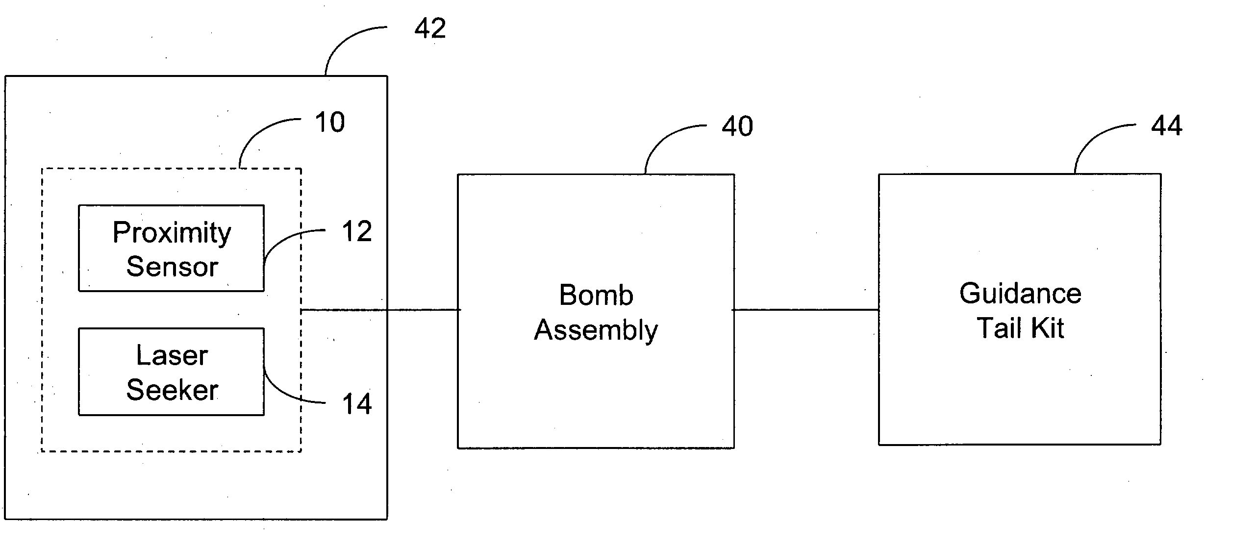
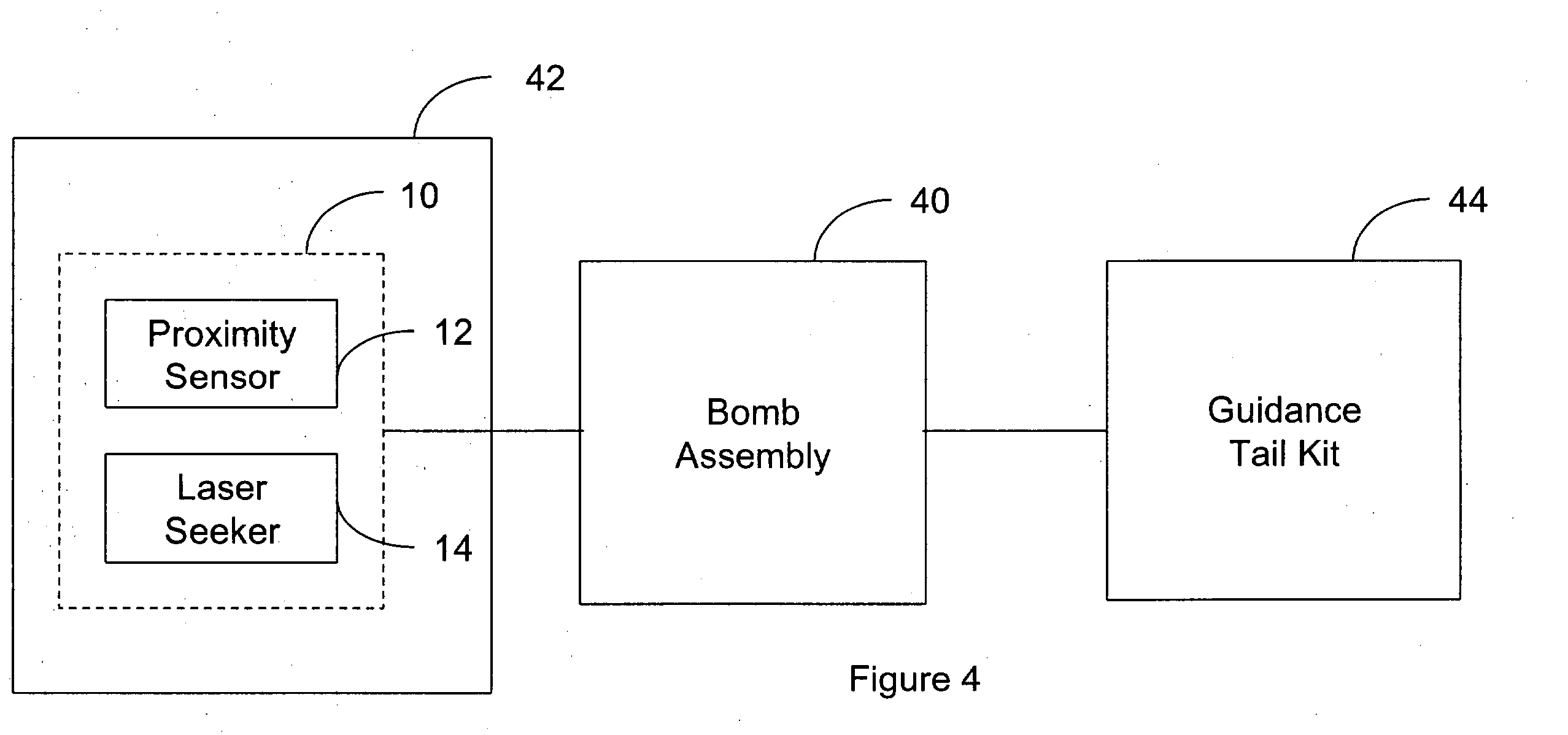
[0026]FIG. 1 shows a radome at 10, and inside the radome is the proximity sensor 12 and laser seeker 14. The proximity sensor can be any proximity sensor such as the commercially available DSU-33B / B all weather, radio frequency ranging radar sensor sold by Alliant Techsystems. This sensor is modified in the invention to add the laser seeker 14, which can either be a focused system or unfocused system, such as the one disclosed in U.S. Pat. No. 6,060,703.

[0027]FIG. 2 shows a focused laser system inside radome 10, with a laser aperture 16 located in the radome, which allows laser radia...


PUM


Abstract

A proximity sensor for use with a guidance system of a smart bomb including a ranging radar proximity sensor configured for mounting on a smart bomb and a radome connected to the ranging radar proximity sensor. A laser radiation sensor system is attached to the proximity sensor, which is configured and arranged to detect laser radiation reflected from a target which passes through the radome and output the azimuth and elevation angles to the target to the guidance system.

Description

CROSS-REFERENCE TO RELATED APPLICATIONS [0001] Not Applicable STATEMENT REGARDING FEDERALLY SPONSORED RESEARCH [0002] Not Applicable BACKGROUND OF THE INVENTION [0003] This invention relates to an improved proximity sensor and more specifically a proximity sensor with an integrated semi-active laser seeker for weapon guidance. [0004] Smart munitions have used a variety of technologies to aid in guiding to a target. These technologies included inertial guided, infrared guided, radar guided, image guided, laser guided, GPS guided, and various combinations of these technologies. [0005] U.S. Pat. No. 4,492,166 is an example of an infrared detector used to detect a target having a higher temperature than the background infrared radiation. U.S. Pat. No. 5,826,819 discloses a weapon system employing a bistatic radar guided transponder bomb and guidance method. U.S. Pat. No. 6,450,442 is an example of an impulse radar guidance system. U.S. Pat. No. 6,157,875 is an example of an image guided...

Claims


Application Information

Patent Timeline
Patent Type & Authority Applications(United States)
IPC IPC(8): F42C13/02
CPCF41G7/226F42C13/02F41G7/2293F41G7/2286
Inventor FRIEDRICH, WILLIAM A.JOHNSON, LYLE H.CONRAD, MARK K.
Owner NORTHROP GRUMMAN SYST CORP
Why Eureka
Try Eureka