Automatic control method used for defrosting a heat pump for a vehicle

a technology of automatic control and heat pump, which is applied in the direction of refrigeration components, transportation and packaging, light and heating equipment, etc., can solve the problems of reducing the efficiency of the heat pump, increasing the electricity consumption for the same performance level, and reducing the performance for the same level of electricity consumption

Inactive Publication Date: 2015-02-12
RENAULT SA
View PDF9 Cites 10 Cited by
  • Summary
  • Abstract
  • Description
  • Claims
  • Application Information

AI Technical Summary

Benefits of technology

[0014]This is because complete defrosting of the external exchanger optimized in terms of time and power consumption does not permit complete defrosting of the accumulator. In fact, the thickness of the frost on the latter may increase, depending on the external conditions and the driving conditions. At a certain point, it becomes necessary to defrost it, because the associated thickness increases its proximity to other parts of the vehicle (with risk of noise and damage) and decreases its performance. It is therefore useful to ascertain the frosting associated with these two elements in order to carry out the appropriate defrosting operation.
[0017]In a specific embodiment, the operation of defrosting the external exchanger or the accumulator comprises a step of putting the compressor into operation at a first predetermined motor speed, in order to cause hot refrigerant fluid to flow in the external heat exchanger and the accumulator for a duration which is less than or equal to a third predetermined maximum duration C3, said motor speed and said third maximum duration being a function of said defrosting operation. The flow of this hot refrigerant fluid makes it possible to melt the frost present on the outer walls of the external exchanger and, if necessary, the frost present on the outer walls of the accumulator.
[0025]Advantageously, an operation of defrosting the external exchanger or the accumulator is started only if the speed of the vehicle is less than or equal to a predetermined speed of 30 km / h or below. This is because it may be considered that there is no point in starting a defrosting operation above this value, since even if the external exchanger or the accumulator has hot fluid flowing through it, the cold air flowing through the external exchanger will keep the frost present.

Problems solved by technology

This frosting of the external exchanger then leads to a decrease in the efficiency of the heat pump, which increases the electricity consumption for the same performance level, or reduces the performance for the same level of electricity consumption.
This also reduces the maximum power of the system.
This solution is not satisfactory, because it increases the total electricity consumption of the system, which has negative effects in the case of electric or hybrid vehicles.
However, other parts of the heat pump become frosted, notably the low pressure pipes and the accumulator, which is detrimental to the performance of the heat pump and which, because of the successive accumulation of frost on the walls of these elements and the proximity of other elements in the immediate environment, risks causing noise and may result in consequential damage.
Therefore, frost forms on the walls of these elements as well, when the external temperature is low.
Furthermore, during the defrosting of the external exchanger, the temperature of the fluid supplied to the accumulator has already fallen considerably because said fluid has already released much of its heat in the external exchanger to cause the melting of the frost present on the walls of the latter.
This presence of frost on the accumulator has the disadvantage that it not only lowers the performance of the heat pump by keeping the fluid contained in the accumulator at a low temperature, but also increases the proximity of the exchanger to other parts of the vehicle, thus increasing the risk of impact with these other parts, increasing the risk of noise due to these impacts, and increasing the risk of degradation of the accumulator and of these parts.

Method used


Image

  • Automatic control method used for defrosting a heat pump for a vehicle
  • Automatic control method used for defrosting a heat pump for a vehicle
  • Automatic control method used for defrosting a heat pump for a vehicle

Examples


first embodiment

[0047]FIG. 5 is a flow diagram showing the main steps of the method of the invention,

[0048]FIG. 6 is a flow diagram showing the sub-steps of the defrosting operation of FIG. 5, and

second embodiment

[0049]FIG. 7 is a flow diagram showing the main steps of the method of the invention, and

third embodiment

[0050]FIG. 8 is a flow diagram showing the main steps of the method of the invention.

DETAILED DESCRIPTION OF AT LEAST ONE EMBODIMENT

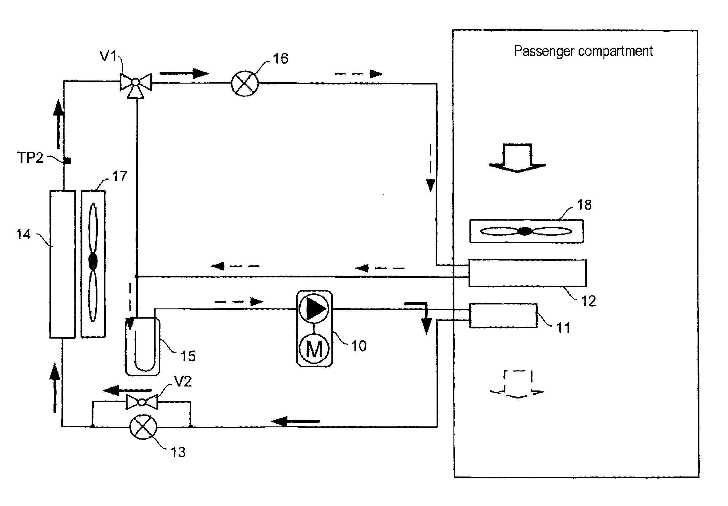
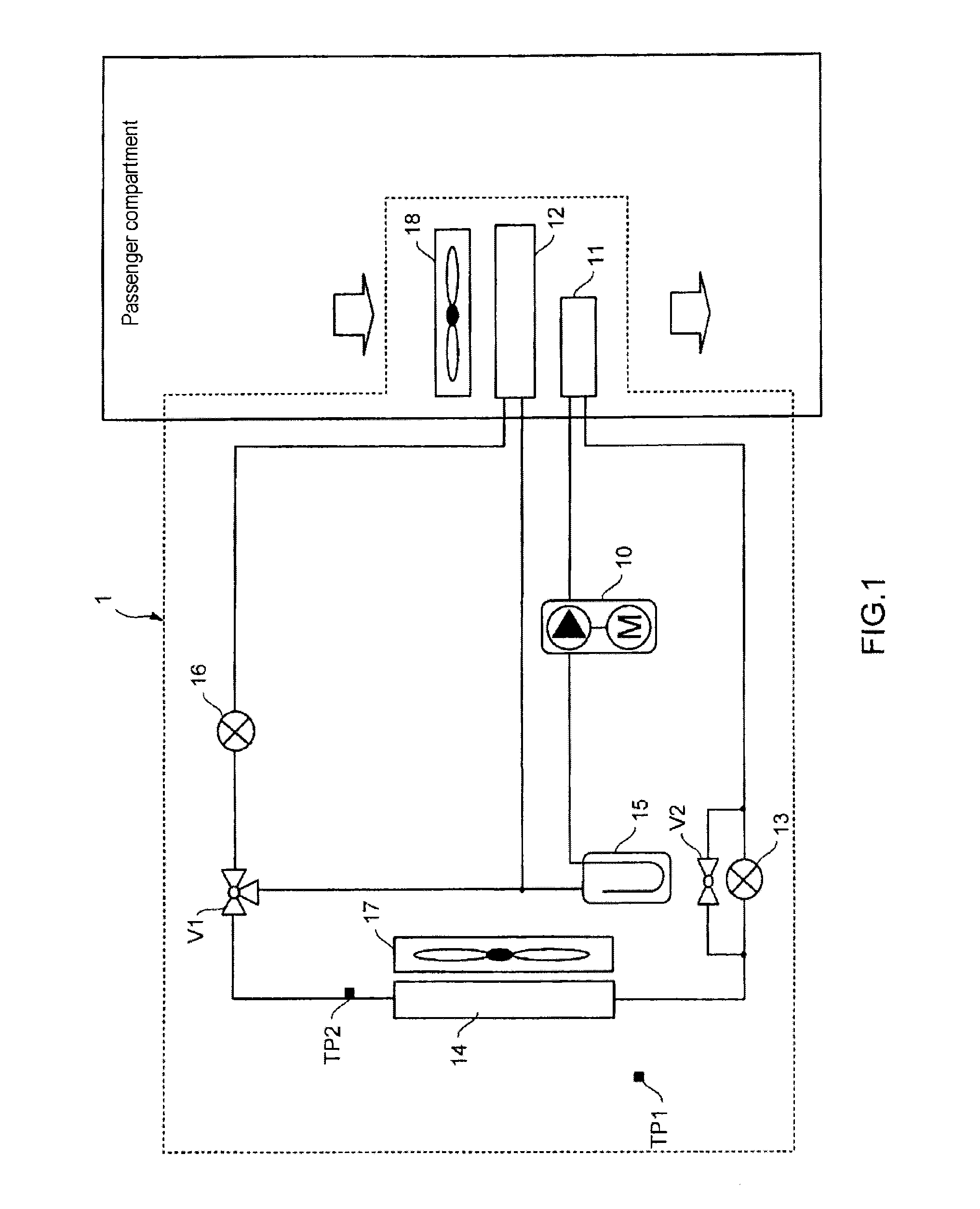
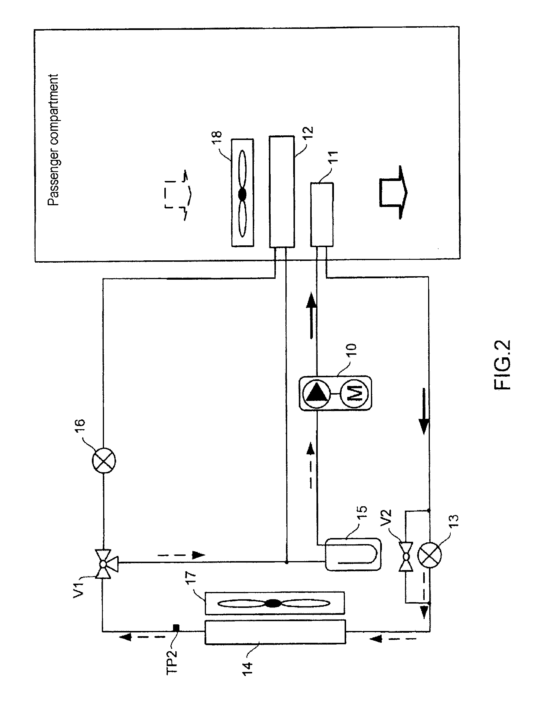
[0051]FIG. 1 shows a heat pump system 1 for which the method of the invention can be used. This system includes a compressor 10, an internal heat exchanger 11 forming an internal condenser in heating mode, another internal heat exchanger 12 forming an internal evaporator in air conditioning mode, an expansion valve 13 for the heating mode, an external heat exchanger 14 forming an evaporator in heating mode, an expansion valve 16 for the air conditioning mode, and an accumulator 15. These various components have a refrigerant fluid flowing through them. Valves V1 and V2 are also provided to modify the path of a refrigerant fluid through these various components according to one of the following operating modes of the system:[0052]in heating mode, the system heats the internal air of the passenger compartment of the vehicle; this operating mode is shown i...


PUM


Abstract

A control method for a heat pump system, or for a motor vehicle, which includes a compressor, an internal heat exchanger forming a condenser in a heating mode, an expansion valve, an outer heat exchanger forming an evaporator in the heating mode, and an accumulator. The defrosting of the outer exchanger is detected, the defrosting of the accumulator is detected, and depending on the case, defrosting the outer exchanger and / or defrosting the accumulator is started.

Description

TECHNICAL FIELD[0001]The present invention relates to the field of heat pump systems fitted to some types of motor vehicles, notably electric or hybrid vehicles. More specifically, it relates to a control method for the heat pump system of these vehicles, said method being used to defrost some components of said system when the external air temperature is low.PRIOR ART[0002]There is a known way of using a heat pump in vehicles for heating and / or air conditioning the passenger compartment of the vehicle. This heat pump is reversible so that it can operate in both heating mode and air conditioning mode. It conventionally comprises a compressor for heating and compressing a refrigerant fluid, an internal heat exchanger forming a condenser in heating mode for heating the internal air in the passenger compartment of the vehicle by heat exchange with the refrigerant fluid flowing from the compressor, an expansion valve for cooling the refrigerant fluid flowing from the internal heat excha...

Claims


Application Information

Patent Timeline
Patent Type & Authority Applications(United States)
IPC IPC(8): B60H1/32F25B47/02
CPCB60H1/3213F25B47/025B60H1/321B60H1/00921
Inventor QUETANT, EUDESGOUTAL, VIRGINIEPASQUINI, MYRIAM
Owner RENAULT SA
Why Eureka
Try Eureka