Magnetically propelled engine with magnetic field reduction

a technology of magnetic field reduction and engine, applied in the field of magnetic field reduction, can solve the problems of reducing the size of the outward electromagnet, the very inefficient engine, and the inefficient engine, so as to reduce the diameter of the piston, maintain the strength of the piston magnet, and facilitate installation and removal.

Active Publication Date: 2012-12-04
KELLER MR CHRISTIAN HARVEY
View PDF24 Cites 10 Cited by
  • Summary
  • Abstract
  • Description
  • Claims
  • Application Information

AI Technical Summary

Benefits of technology

[0011]Although others have invented magnetically driven engines and internal combustion engines, my invention is superior because it converts any internal combustion engine to a magnetically driven engine and engine designers can create new engines employing these magnetic repulsion attraction components and is more versatile by covering all internal combustion engine applications, plus more. Examples this wide range of applications would include are: cars, trucks, tractor trailers, trains, ships, boats, power plants, home electrical generators, other types of electrical generators, farm and lawn equipment, industrial equipment, earth moving equipment, etc. This engine magnetically moves the engine's piston(s) in both inward toward crankshaft and outward directions toward cylinder head. It can employ a simple design with less moving parts than an internal combustion engine. It can run off of a rechargeable battery(s) and be recharged at home; work or anywhere an outlet may be convenient and doesn't require any fuel to run the magnetically powered engine. The only emission is clean air from the magnetically propelled engine. It will not emit pollutants into the environment, like the internal combustion engine. This wasted air can be used to drive an electric turbine or turbo, to create electrical power for the engine to run, and for charging the battery(s) while not taking any horsepower away from the engine.
[0012]The elimination of the extreme heat created from the internal combustion engine and can eliminate the need for a liquid cooling system. This could create a wider range of uses for an oil-less engine with plastic or Teflon piston rings. It will operate a lot cooler than an internal combustion engine and won't contaminate the oil with the harsh chemical residue left behind after combustion, which eventually reduces engine oil life. This gives the ability to go longer between oil changes increasing oil life. Cooler operation of my type of engine and longer life between oil changes without the harsh chemical residue, can significantly increase the engine(s) overall life.
[0013]A new type of hybrid engine made with internal combustion engine components and my magnetically controlled propelled engine components, which will consume less fuel by deriving more power from the electro-magnet(s) through magnetic repulsion and attraction. Be able to perform easy performance upgrades to make an electro magnet repulsive engine produce more power, by easily upgrading to a larger and more powerful electro-magnet(s).
[0015]Of the many patents issued for an electromagnetically or magnetically propelled engines, to the best of my knowledge no electromagnet, electromagnetically or magnetically controlled propelled engines have any kind of magnetic shielding to protect the occupants, people on the outside of the vehicle, engine, or engine compartment from serious bodily harm or death from the strong magnetic fields generated by this type of engine. Shielding of these strong magnetic fields would be to prevent possible interference of pacemakers, other on the person electrical accessory, equipment or items sensitive to strong magnetic fields.

Problems solved by technology

Lack of computer control in Charles Wortham Patent decreases the ability to control every fraction of movement in a vehicle with magnetic engine making the engine a very inefficient magnetically propelled engine.
By today's standard it is a very inefficient engine for the type electromagnets used and the contact switching used to activate the electromagnet.
The size of the axial passageway would have to be almost half or more than half the size of the piston to allow the engine air to freely flow, which would reduce the size of the outward electromagnet size to the point of being a very inefficient engine and increase engine air noise because of the air traveling through the axial passageway at higher engine speeds.
The use of water flowing through the electromagnet coils could short out having premature failure due to engine operation, corrosion and stress on electromagnet coils.
That failure could short out the entire engine's electrical system and with that kind of amperage up to 400 amps could start an electrical fire not easily extinguished.
The problem of oil splash or blowby will be created without the lack of compression and engine crankcase pressure build up while the engine is running.
Failure of one radially oriented row will slightly decrease engine horsepower and would be tolerable under normal operating conditions.
Because the radially oriented rows are mounted in the cylinder walls and the cylinder bore having to be flawless to prevent piston premature wear may make it impossible to repair at all and most likely repair impossible in a vehicle.
The entire engine could become junk if the electromagnets fail or break apart in the cylinder destroying the entire cylinder, cylinder head and piston.

Method used


Image

  • Magnetically propelled engine with magnetic field reduction
  • Magnetically propelled engine with magnetic field reduction
  • Magnetically propelled engine with magnetic field reduction

Examples


Embodiment Construction

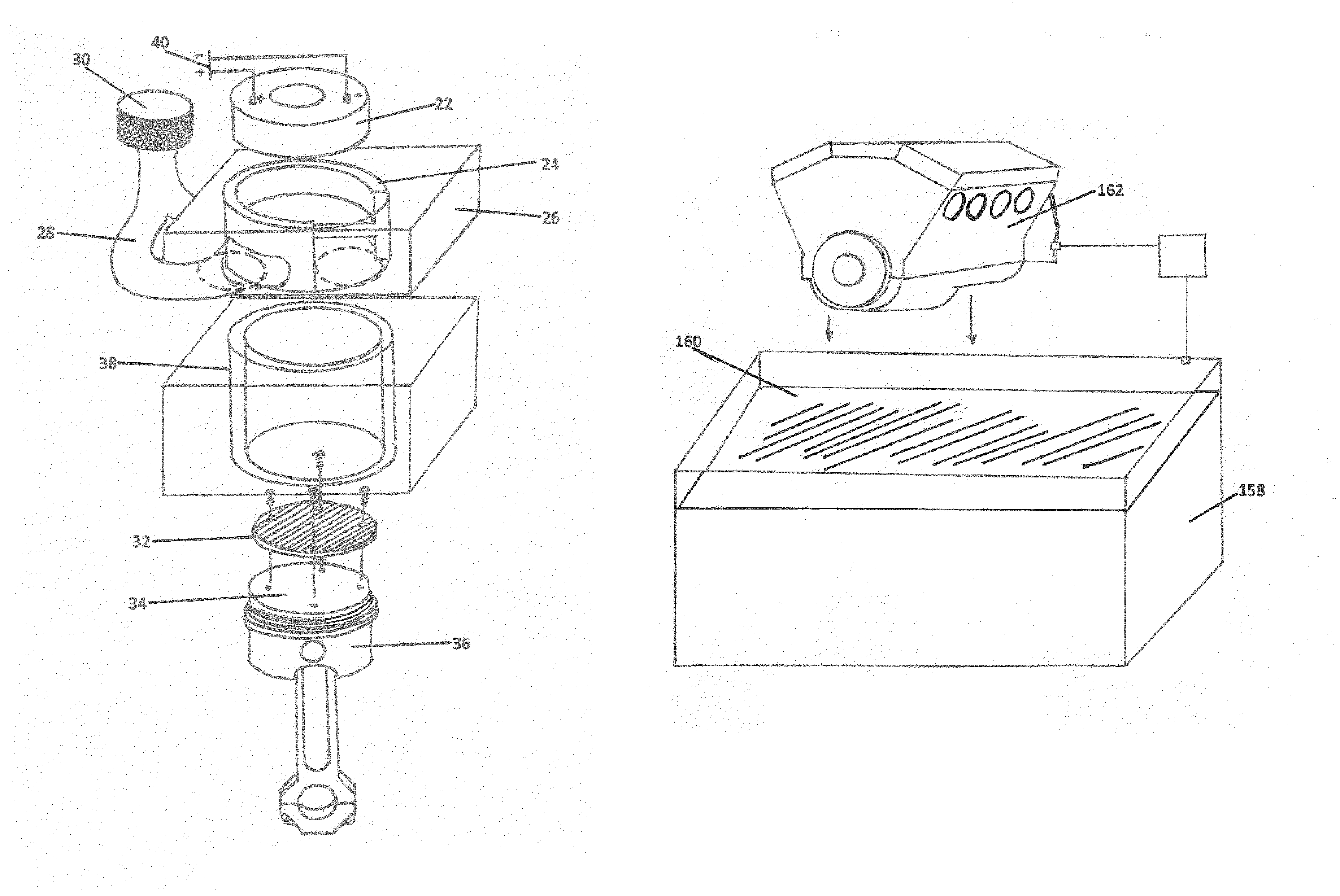
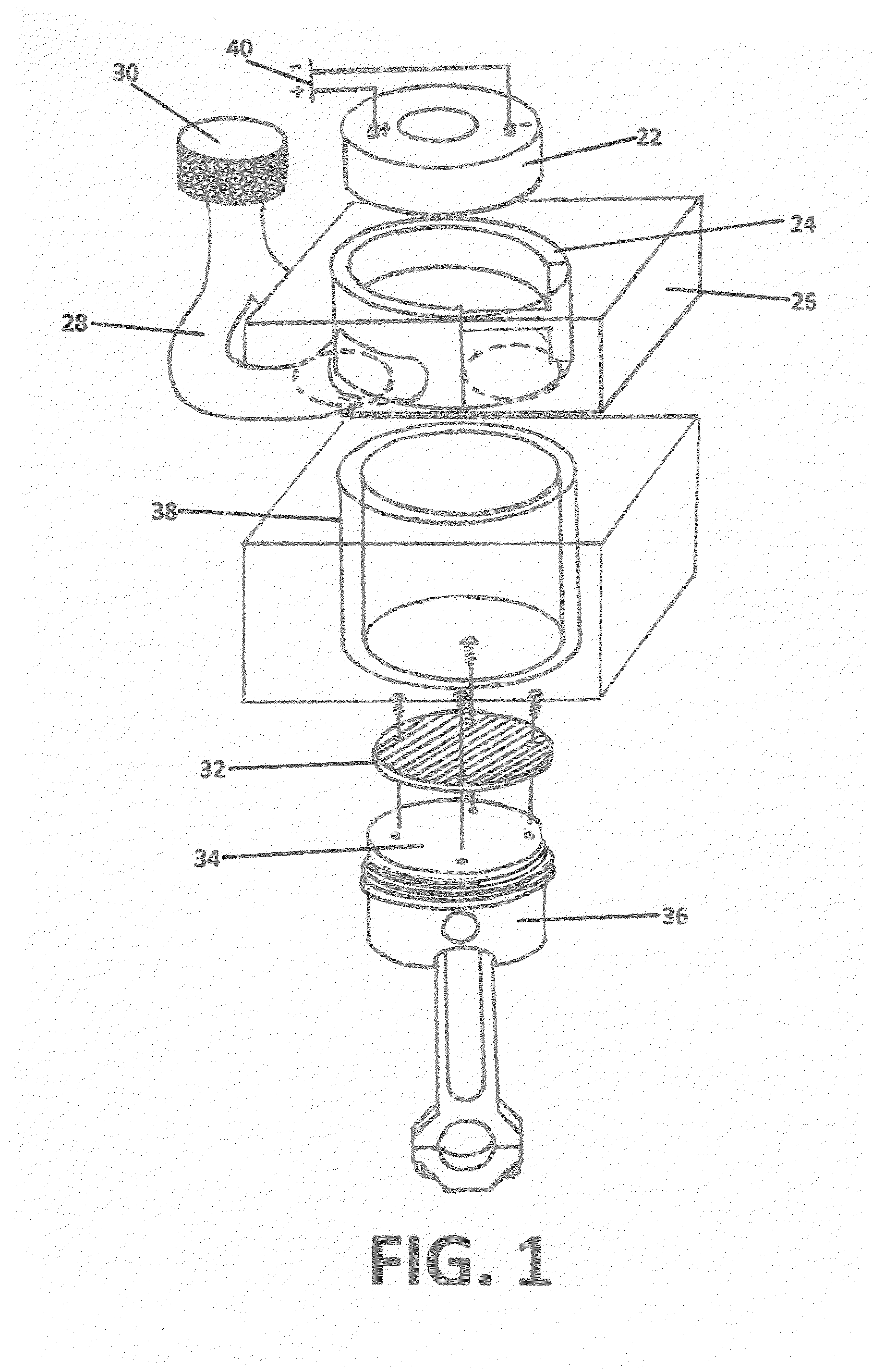
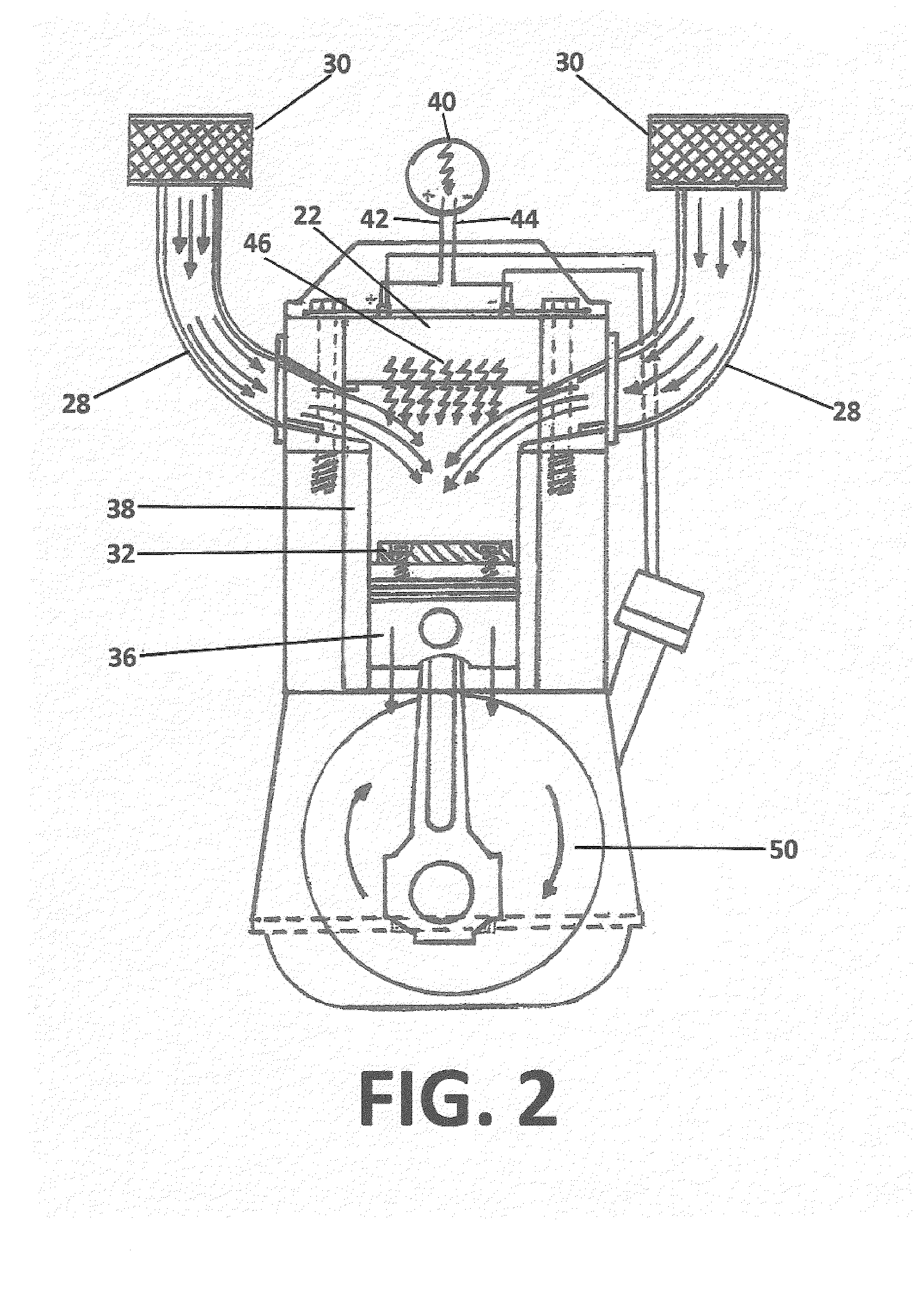
[0039]Referring now to the drawings in full detail, and in particular to FIGS. 1, 4 and 7, which show a view of all the main magnetically controlled propelled engine parts, showing a full 3 dimensional view of the parts, in an exploded view. The main electro magnet(s) 22 is encased in a magnetic reducing, or blocking material 24 in the cylinder head 26 with the intake / exhaust manifold 28 and intake / exhaust filter 30. The repulsive attractive rare earth magnet Neodymium 32 is used for the engine in this application for it lower working operation temperature and attached with high strength glue, adhesive, screw(s), bolt(s) or any combination of them, to the surface of the piston 34. The piston 36 moves by the electro magnet(s) 22 repulsion and attraction of the rare earth magnet 32 and piston 36 upward and downward, inside the cylinder 38. The movements of these parts are accomplished by applying positive and negative electrical power 40 to the electro magnet(s) 22. The application of...


PUM


Abstract

An engine powering device with magnetic components that aid in the operation of piston propelled engines by attaching the device individually to the pistons, causing the pistons to perform the up and down thrusts without the use of fuel combustion thereby mobilizing the engine, eliminating the necessity of fuel and preventing pollution exhausting into the atmosphere. An exemplary system for a magnetically controlled propelled engine that uses exhausted clean air from the engine that flows through an electric generating turbo or turbine to charge the battery to power the engine. Passenger compartment comfort heating is supplied by and electric liquid boiler or liquid heater with a circulation pump. A fuel door mounted universal electrical connector to aid in charging engine battery. This engine has magnetic shielding safety components to protect people and other electronic devices from strong rare earth magnets and electromagnets.

Description

FIELD OF THE INVENTION[0001]This invention relates to a magnetic device, computer controlled to time the piston thrusts on most types of engines, eliminating fuel use, friction, engine heat and exhaust fumes thereby extending the life of the engine, with an exhaust powered charging apparatus that doesn't restrict horsepower, liquid heater with circulating pump for the comfort of heat for passenger(s), universal fuel door charging connector and passenger safety by the way of magnetic shielding.BACKGROUND OF THE INVENTION[0002]Most piston powered engines are spoken of as four-cycle engines. This is a shortening of the correct name, four-stroke cycle. A stroke is one complete down or one complete up movement of the piston. There are two down strokes and two upstrokes to a cycle for the internal combustion engine of this design. A cycle is a round of events, which occurs in a certain fixed order.[0003]There are four events in this engine cycle. These four events correspond to the four s...

Claims


Application Information

Patent Timeline
Patent Type & Authority Patents(United States)
IPC IPC(8): H02K7/075
CPCH02K53/00
Inventor KELLER, CHRISTIAN HARVEY
Owner KELLER MR CHRISTIAN HARVEY
Why Eureka
Try Eureka