Power converting system with function of reducing dead-time

a technology of power conversion system and dead-time reduction, which is applied in the direction of power conversion system, process and machine control, instruments, etc., can solve the problems of reducing the efficiency of pwm/pfm circuit, power switch overheating and even breaking down, and easy to affect the generated dead-time, etc., and achieve the effect of reducing dead-tim

Inactive Publication Date: 2012-12-04
PRINCETON TECH CORP
View PDF4 Cites 9 Cited by
  • Summary
  • Abstract
  • Description
  • Claims
  • Application Information

AI Technical Summary

Benefits of technology

[0005]The present invention provides a driving circuit with function of reducing dead-time. The driving circuit comprises a dead-time detecting circuit, a duty-cycle controlling circuit, and a switch-controlling circuit. The dead-time detecting circuit is coupled to an output of a power switch set for detecting a switching voltage on the output of the power switch set and accordingly generating a dead-time detecting signal. The output of the power switch set is coupled to a first end of an inductive load. A second end of the inductive load provides an output voltage. The duty-cycle controlling circuit is coupled to the second end of the inductive load. The duty-cycle controlling circuit is utilized for generating a set / reset signal according to the output voltage. The switch-controlling circuit is utilized for changing the state of the power switch set from a dead-time state according to the set / reset signal and the dead-timed detecting signal.
[0006]The present invention further provides a power converting system with function of reducing dead-time. The power converting system comprises a power switch set, a dead-time detecting circuit, a duty-cycle controlling circuit, and a switch-controlling circuit. The power switch set is coupled to an inductive load. The power switch set has a first power switch and a second power switch. The power switch set is controlled to be away from a dead-time state according to a first switch-driving signal and a second switch-driving signal. The dead-time detecting circuit is coupled to a first end of the inductive load. The dead-time detecting circuit is utilized for detecting a switch voltage on the first end of the inductive load and accordingly generating a dead-time detecting signal. The duty-cycle controlling circuit is coupled to a second end of the inductive load. The duty-cycle controlling circuit is utilized for generating a set / reset signal according to an output voltage of the power converting system. The switch-controlling circuit is utilized for generating the first switch-controlling signal and the second switch-controlling signal according to the set / reset signal and the dead-time detecting signal.

Problems solved by technology

In the prior art, the dead-time generator is composed only of logic gates so that the generated dead-time is easily affected by the fabrication or the temperature.
If the generated dead-time is too short, then the power switches of the output-stage circuit of the PWM / PFM circuit may be simultaneously turned-on, generating the large current, causing the power switches overheated and even broken-down.
If the generated dead-time is too long, the efficiency of the PWM / PFM circuit is reduced.

Method used


Image

  • Power converting system with function of reducing dead-time
  • Power converting system with function of reducing dead-time
  • Power converting system with function of reducing dead-time

Examples


Embodiment Construction

[0016]The present invention provides a power converting system capable of determining if the power converting system is in a dead-time state. When the power converting system is in the dead-time state, the corresponding power switch is turned on in time for reducing the dead-time and improving the efficiency.

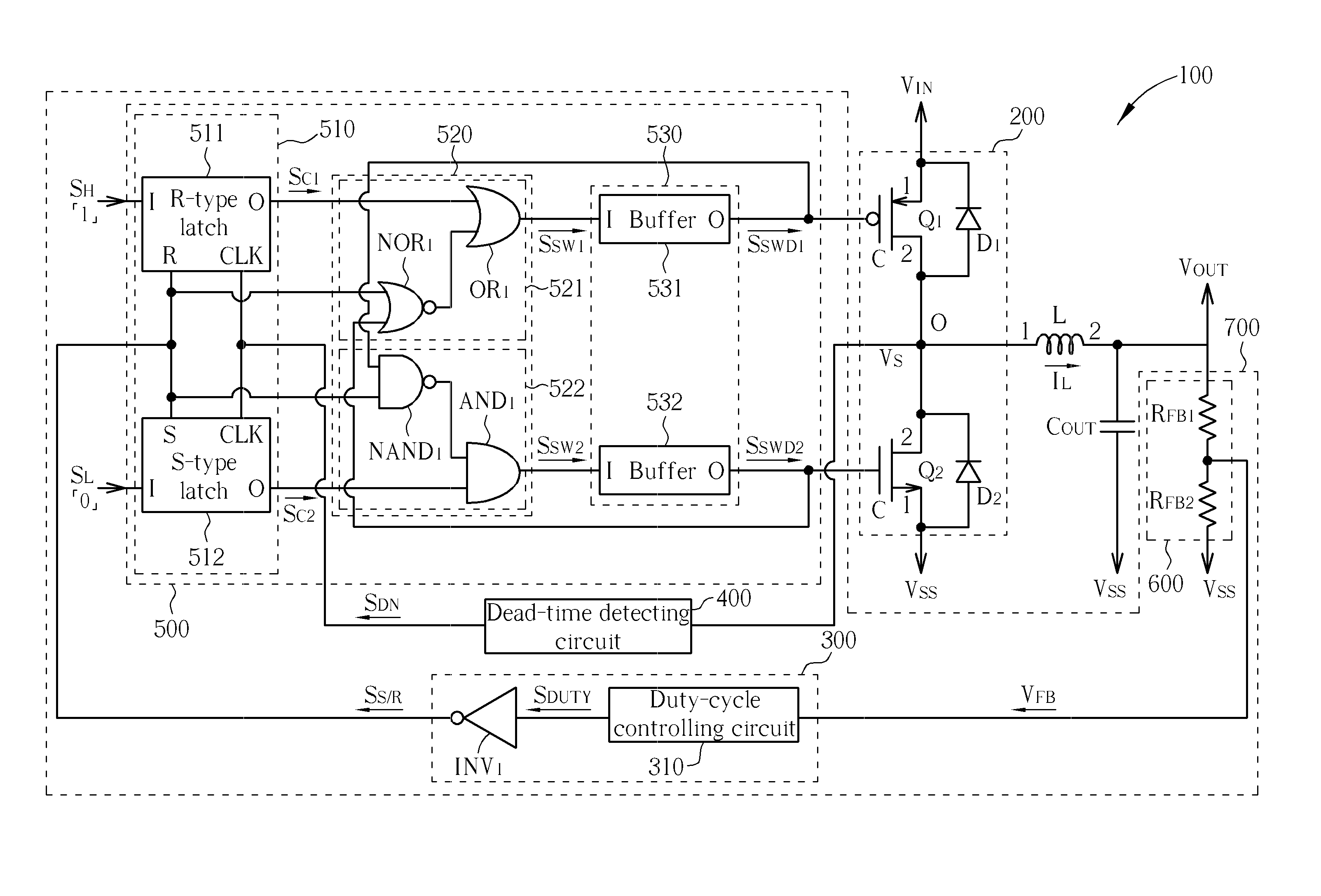
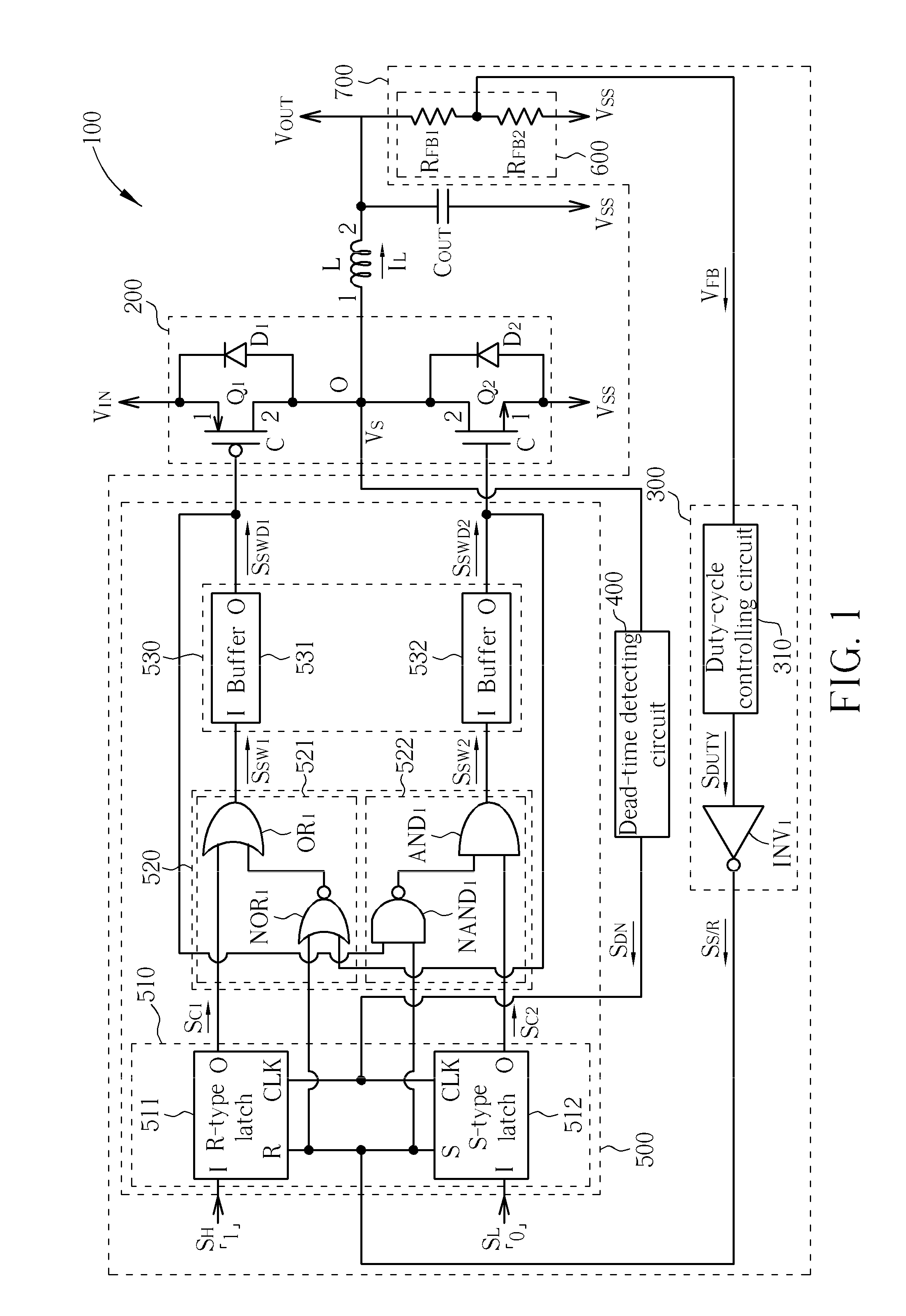
[0017]Please refer to FIG. 1. FIG. 1 is a diagram illustrating a power converting system 100 according to a preferred embodiment of the present invention. The power converting system 100 can be determined to operate in a Continuous Current Mode (CCM) or in a Discontinuous Current Mode (DCM) for converting an input voltage source VIN into an output voltage source VOUT. The power converting system 100 comprises a driving circuit 700, a power switch set 200, an inductive load L, and an output capacitor COUT. The power switch set 200 comprises power switches Q1 and Q2. In the power converting system 100, the power switch set 200 can be treated as a PWM / PFM circuit. The power switch ...


PUM


Abstract

A driving circuit includes a dead-time detecting circuit, a duty-cycle controlling circuit, and a switch controlling circuit. The dead-time detecting circuit is coupled to an output of a power switch set for detecting a switching voltage on the output of the power switch set and accordingly outputting a dead-time detecting signal. The output of the power switch set is coupled to the first end of an inductive load, and the second end of the inductive load provides an output voltage. The duty-cycle controlling circuit is coupled to the second end of the inductive load for generating a set / reset signal according to the output voltage. The switch controlling circuit controls the power switch set to be away from a dead state according to the set / reset signal and the dead-time detecting signal.

Description

BACKGROUND OF THE INVENTION[0001]1. Field of the Invention[0002]The present invention relates to a power converting system, and more particularly, to a power converting system with function of reducing the dead-time.[0003]2. Description of the Prior Art[0004]In the PWM / PFM circuit, controlling the dead-time is very important. In the prior art, the dead-time generator is composed only of logic gates so that the generated dead-time is easily affected by the fabrication or the temperature. If the generated dead-time is too short, then the power switches of the output-stage circuit of the PWM / PFM circuit may be simultaneously turned-on, generating the large current, causing the power switches overheated and even broken-down. If the generated dead-time is too long, the efficiency of the PWM / PFM circuit is reduced. Therefore, in design for the PWM / PFM circuit, the dead-time has to be properly designed and steadily controlled.SUMMARY OF THE INVENTION[0005]The present invention provides a d...

Claims


Application Information

Patent Timeline
Patent Type & Authority Patents(United States)
IPC IPC(8): G05F1/00
CPCH02M1/38
Inventor WANG, WEIKUO, CHIEN-HUNGCHANG, CHUN
Owner PRINCETON TECH CORP
Why Eureka
Try Eureka