
System and method for battery conservation in a portable device

a portable device and battery technology, applied in the field of system and method for battery conservation in a portable device, can solve the problems of user unfriendly approach, unwanted illumination cycles, and detriment to battery life, and achieve the effect of reducing or eliminating the activation period of energy-consuming features, and minimizing the detrimental effect of false triggers

Active Publication Date: 2012-12-04
UNIVERSAL ELECTRONICS INC
View PDF8 Cites 2 Cited by
  • Summary
  • Abstract
  • Description
  • Claims
  • Application Information

AI Technical Summary

Benefits of technology

"This patent relates to battery-powered devices that have a feature that consumes energy, such as a backlight or a keypad. To prevent false triggers that activate the energy-consuming feature, the device has an algorithm that detects false triggers and reduces or eliminates the activation period of the feature. This can happen gradually or all at once, depending on the feature. The device can automatically restore normal operation after a certain period of time or with specific user input. The technical effect of this patent is to improve the accuracy and efficiency of battery-powered devices that have energy-consuming features."

Problems solved by technology

In order to conserve battery power, such devices may only energize the backlighting circuitry for a predetermined period of time after a user interacts with a device input means, e.g., by pressing a key, touching a touch screen surface, or the like.
Such an approach may however be perceived as user unfriendly since it requires that a user perform a possibly unnecessary interaction with the device in order to activate the illumination.
Such systems however suffer from the disadvantage that background vibration or other unintentional movement of the device may trigger unwanted illumination cycles to the detriment of battery life.

Method used


Image

  • System and method for battery conservation in a portable device
  • System and method for battery conservation in a portable device
  • System and method for battery conservation in a portable device

Examples


Embodiment Construction

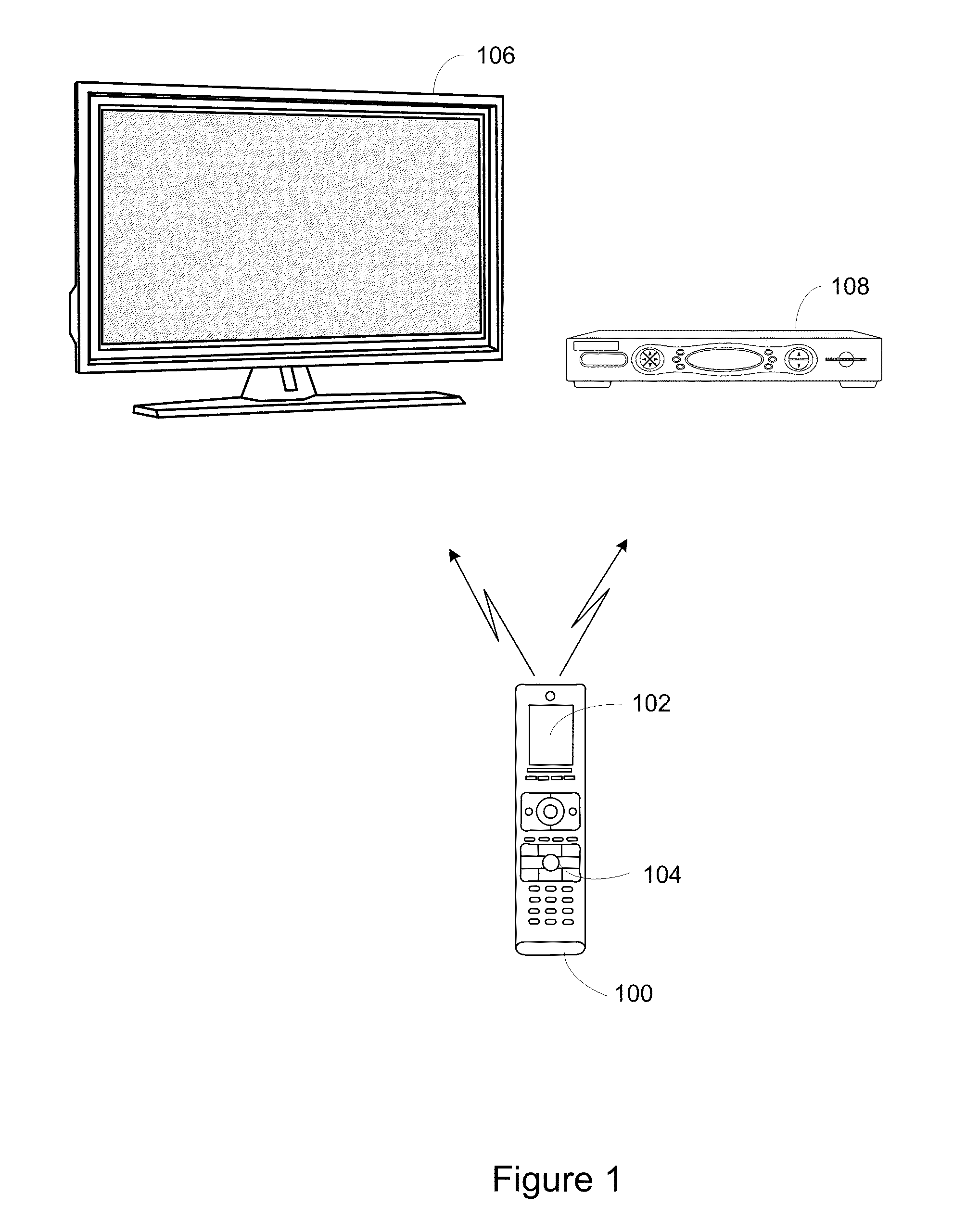
[0009]Turning now to FIG. 1, an exemplary system is illustrated having a battery powered device 100 comprising an energy consuming feature, e.g. a backlight, that is controllable in accordance with the teachings hereinafter described to account for false triggering responses. In the example illustrated in FIG. 1, the battery powered device is in the form of a backlit controlling device which is configurable to control various appliances, such as a television 106 and a set top box (“STB”) 108. As is known in the art, the controlling device 100 is capable of transmitting commands to the appliances, using any convenient IR, RF, Point-to-Point, or networked protocol, to cause the appliances to perform operational functions. Controlling device 100 is further equipped with a backlit LCD display 102, and in some embodiments backlit keys 104, both as are well known in the art. Backlight activation and the duration thereof is under the control of the operating program of controlling device 1...


PUM


Abstract

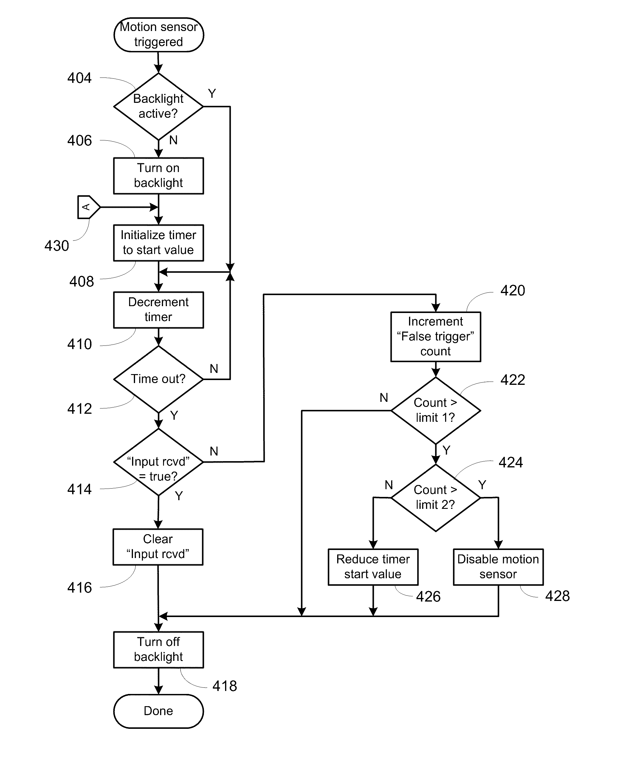
A hand-held device, such as a remote control, has a time-limited feature, such as backlight illumination, that is caused to be activated upon the occurrence of a triggering event sensed by a triggering sensor, such as a motion sensor. The hand-held device functions to disable and / or downwardly adjust a time period during which the time-limited feature will be allowed to be active upon a future occurrence of a triggering event in response to the device determining that a predetermined number of trigger events sensed via the triggering sensor are false trigger events. The time-limited feature may be disabled by disabling the triggering sensor.

Description

BACKGROUND[0001]Battery powered portable devices such as remote controls, mobile phones, cordless phone handsets, PDAs, Web tablets, e-books, etc., frequently employ backlighting techniques to illuminate keys, activate LCD screens, etc., as is well known in the art. In order to conserve battery power, such devices may only energize the backlighting circuitry for a predetermined period of time after a user interacts with a device input means, e.g., by pressing a key, touching a touch screen surface, or the like. Such an approach may however be perceived as user unfriendly since it requires that a user perform a possibly unnecessary interaction with the device in order to activate the illumination. Accordingly, as an alternative (or in addition to), some devices may incorporate motion, tilt, or vibration sensing means in order to respond to a user touching or handling the device generally by automatically energizing the backlighting circuitry, i.e., backlight illumination is caused wi...

Claims


Application Information

Patent Timeline
Patent Type & Authority Patents(United States)
IPC IPC(8): H04B1/38
CPCG08C17/02H04W52/0254G08C2201/32G08C2201/51G08C2201/93H04M2250/12H04W52/027G06F1/1694G06F1/3203G06F1/3231G06F1/3265H04N21/42204H04N21/42208H04N21/4222H04N21/42222H04N21/42224Y02D10/00Y02D30/70
Inventor YOUNG, RICHARDCHAMBERS, CHRISTOPHER
Owner UNIVERSAL ELECTRONICS INC
Learn More