
Laser-assisted production method for a gearing component and gearing

a technology of gearing and component, applied in the direction of electron beam welding apparatus, gear teeth, furnace types, etc., can solve the problems of reducing the mechanical load-bearing capacity of the unfinished tooth-system part, and achieve the effects of increasing the demands on all components, increasing the utilization rate of materials, and increasing power density

Inactive Publication Date: 2019-11-07
FLENDER GMBH
View PDF0 Cites 1 Cited by
  • Summary
  • Abstract
  • Description
  • Claims
  • Application Information

AI Technical Summary

Benefits of technology

The present invention relates to a method for producing a strong tooth system for gearing components. The method uses a laser to remove residual oxide layers without affecting the heat treatment process, which results in improved strength and greater material utilization. The laser acts on a small area of the tooth system, minimizing detrimental effects caused by residual oxide layers while retaining the benefits of heat treatment such as residual compressive stresses. The gearing component produced using this method has improved strength and can be designed for weight-saving and material utilization purposes.

Problems solved by technology

The heat treatment results in the formation on a surface of the unfinished tooth-system part of an oxide layer which reduces mechanical load-bearing capacity of the unfinished tooth-system part.

Method used


Image

  • Laser-assisted production method for a gearing component and gearing
  • Laser-assisted production method for a gearing component and gearing
  • Laser-assisted production method for a gearing component and gearing

Examples


first embodiment

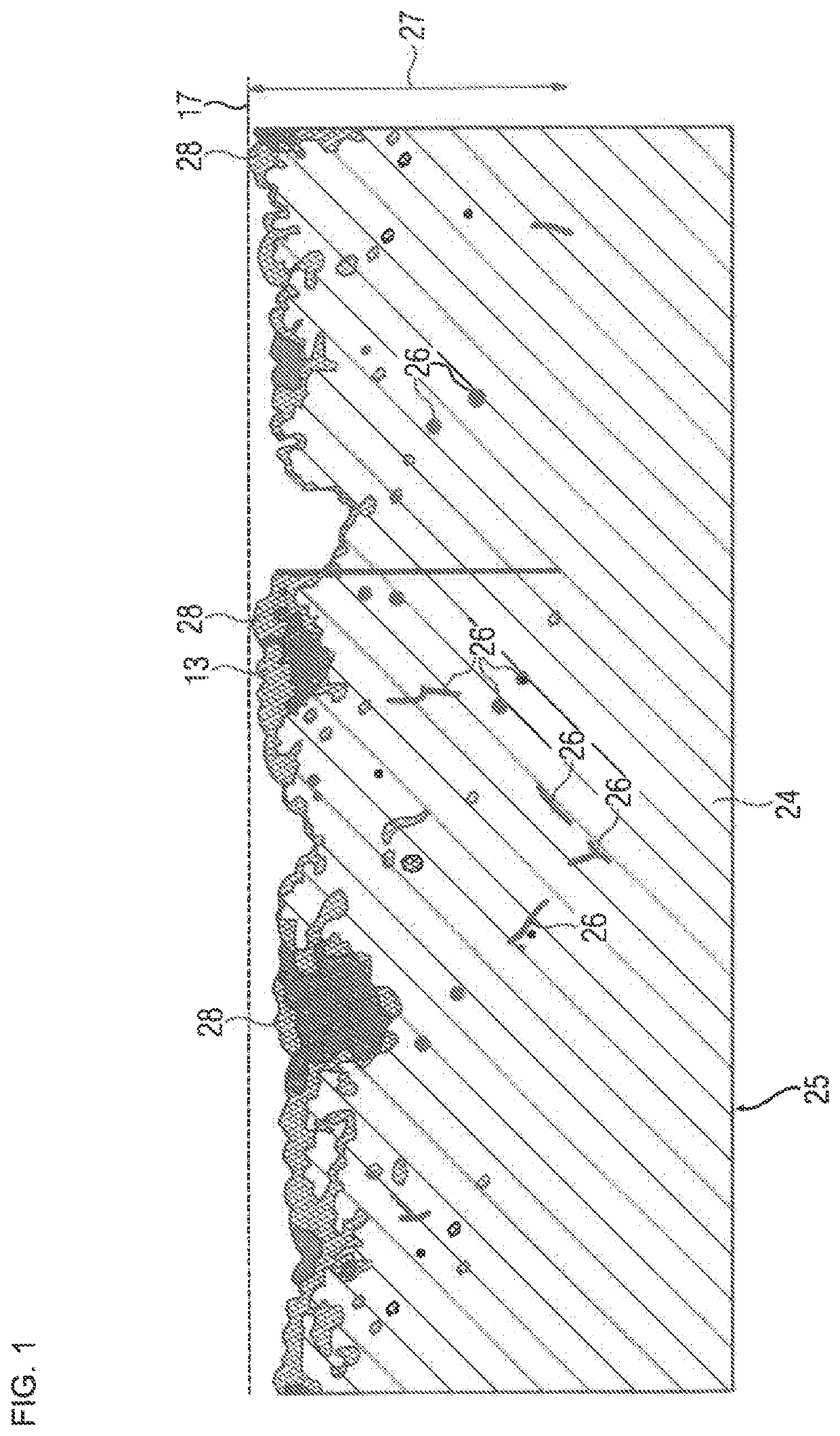
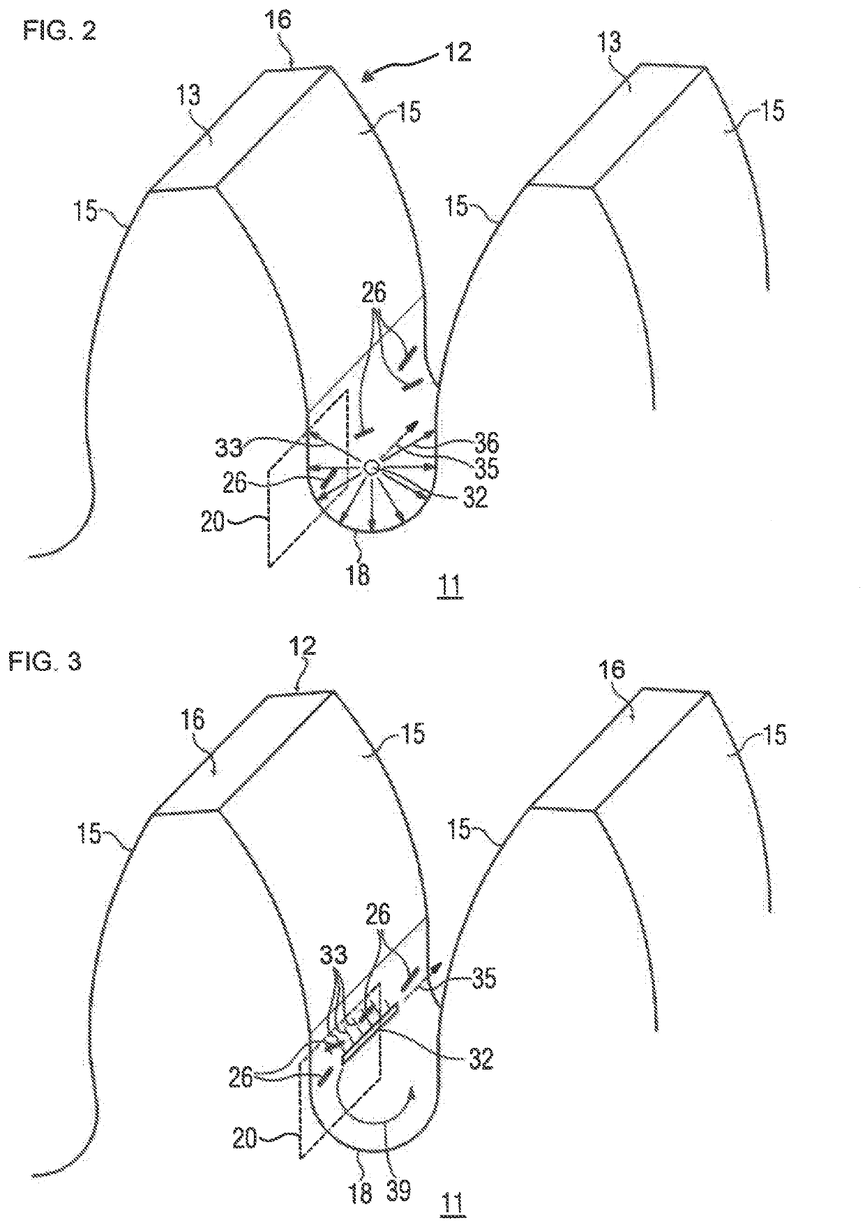
[0032]FIG. 2 shows schematically a segment of the unfinished tooth-system part 25, which is to be processed into a gearing component, such as a gear tooth 16. The unfinished tooth-system part 25 includes a main body 11, on which the tooth system 12 is to be formed. FIG. 2 represents a schematic view of the unfinished tooth-system part according to a method of the present invention. The tooth system 12 has a plurality of teeth 16. After undergoing the heat treatment, in particular case hardening, in method step 110, and partial removal of the oxide layer formed thereby on the surface 13 in method step 120, a residual oxide layer is formed on a tooth flank 15 in the region of a tooth base 18. The residual oxide layer includes oxide inclusions 26, which are contained in the surface 13. During the third method step 130 depicted in FIG. 2, a processing region 20 on the surface 13 of the unfinished tooth-system part 25 is irradiated. A laser 32 associated with a laser unit 30 (FIG. 4) per...

second embodiment

[0034]FIG. 3 shows schematically the third method step 130. Same reference characters in FIG. 3 have a same technical meaning as in FIG. 2. According to the embodiment shown in FIG. 3, the laser beams 33 in the processing region 20 are directed substantially linearly onto the surface 13. In addition to a processing movement 35 along the tooth base 18, a rotational movement of the laser 32 as indicated by arrow 39 is executed. During the rotational movement 39, by virtue of a known profile of the surface 13 in the region of the tooth flanks 15 and of the tooth base 18, it is easily possible to adjust the settings of the laser 32, in particular the focal-point distance 36. This allows the laser 32 to be adapted easily to the shape of the unfinished tooth-system part 25 to be processed, and provides particularly thorough removal of the residual oxide layer. This is accordingly repeated portion by portion for a plurality of processing regions 20.

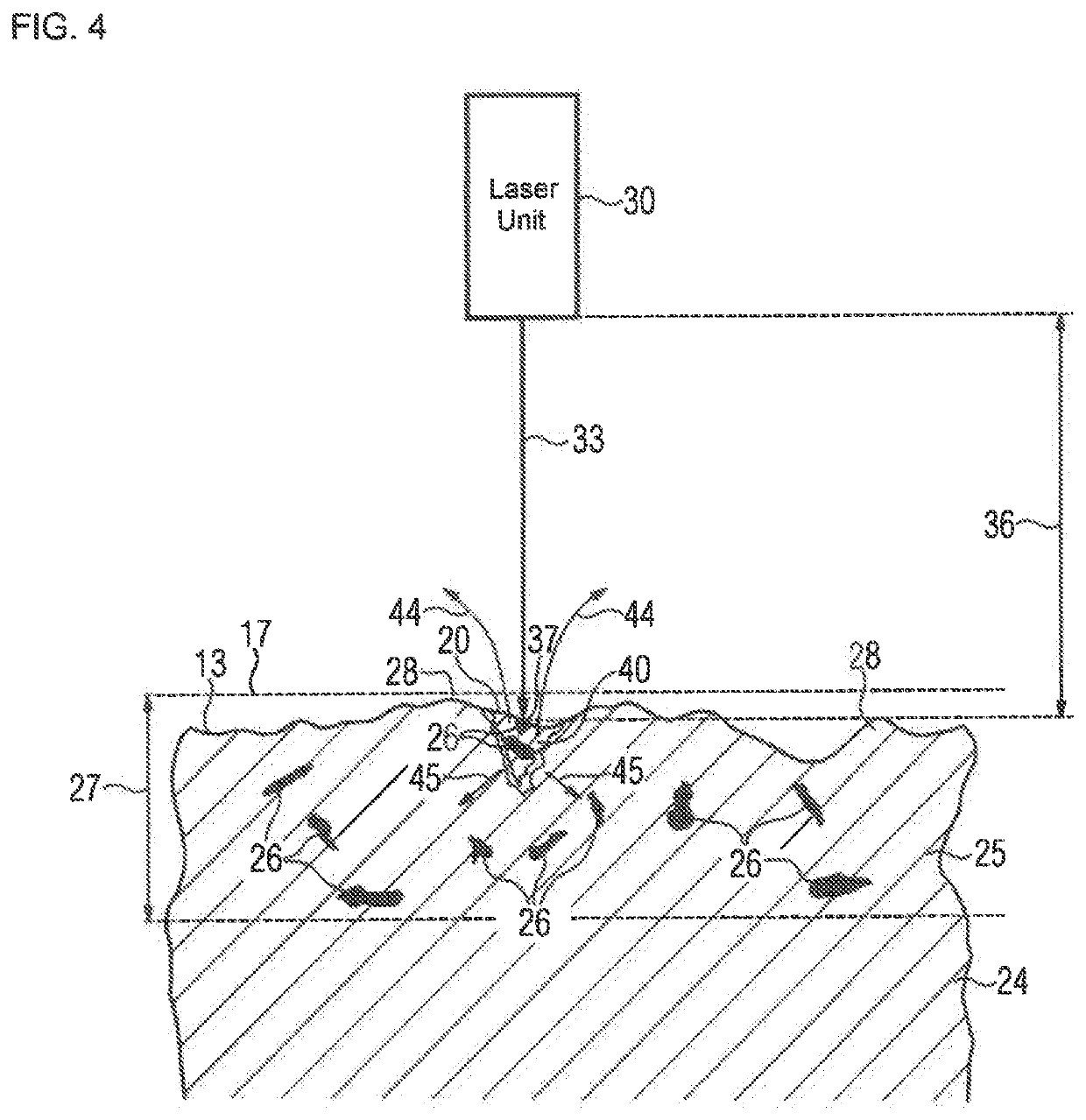
[0035]FIG. 4 shows a schematic microscopi...


PUM

PropertyMeasurementUnit
thicknessaaaaaaaaaa
depthaaaaaaaaaa
thicknessaaaaaaaaaa

Abstract

In a method for making a tooth system of a gearing component, an unfinished tooth-system part is heat-treated. At least part of an oxide layer on the unfinished tooth-system part is mechanically removed, while leaving a residual oxide layer in at least one region, and the residual oxide layer is at least partially removed by irradiating with a laser at least a portion of the residual oxide layer.

Description

CROSS-REFERENCES TO RELATED APPLICATIONS[0001]This application claims the priority of European Patent Application, Serial No. 18170551.8, filed May 3, 2018, pursuant to 35 U.S.C. 119(a)-(d), the disclosure of which is incorporated herein by reference in its entirety as if fully set forth herein.BACKGROUND OF THE INVENTION[0002]The present invention relates to a method for producing a tooth system on a gearing component, to a computer program product, and to a processing apparatus for implementing the production method. The present invention also relates to a gearing.[0003]The following discussion of related art is provided to assist the reader in understanding the advantages of the invention, and is not to be construed as an admission that this related art is prior art to this invention.[0004]Gear-system engineering seeks to achieve ever greater power densities, resulting in increasing demands on all the components in a gearing system. In particular, there is a requirement both for ...

Claims


Application Information

Patent Timeline
Patent Type & Authority Applications(United States)
IPC IPC(8): B23K20/24B23K15/00B23K26/361
CPCB23K26/361B23K20/24B23K15/0033B23F17/00B23K26/00B23K26/352B23K26/354B23K26/36B23K26/0093B23K26/032B23K26/60B23K2101/008B23K2103/04B23P15/14C21D1/06C21D1/09C21D9/32C21D2261/00
Inventor MEIS, JEAN-ANDRE
Owner FLENDER GMBH
Learn More