Deployable ramp assembly

a technology for deploying ramps and assembly parts, which is applied in the direction of hand carts, medical transportation, transportation items, etc., can solve the problems of movable parts that may become disengaged, jammed, and misaligned, and the typical drive mechanism of such ramp assemblies is usually relatively complex

Active Publication Date: 2012-12-11
FEDICO
View PDF40 Cites 10 Cited by
  • Summary
  • Abstract
  • Description
  • Claims
  • Application Information

AI Technical Summary

Benefits of technology

[0004]It is therefore an aim of the present invention to provide an improved deployable ramp assembly.

Problems solved by technology

Typical drive mechanisms for such ramp assemblies, e.g. gear mechanisms, chain drives, belt drives, and combinations thereof, are usually relatively complex, with a number of movable parts that may become disengaged, jammed, misaligned, etc. during use.

Method used


Image

  • Deployable ramp assembly
  • Deployable ramp assembly
  • Deployable ramp assembly

Examples


Embodiment Construction

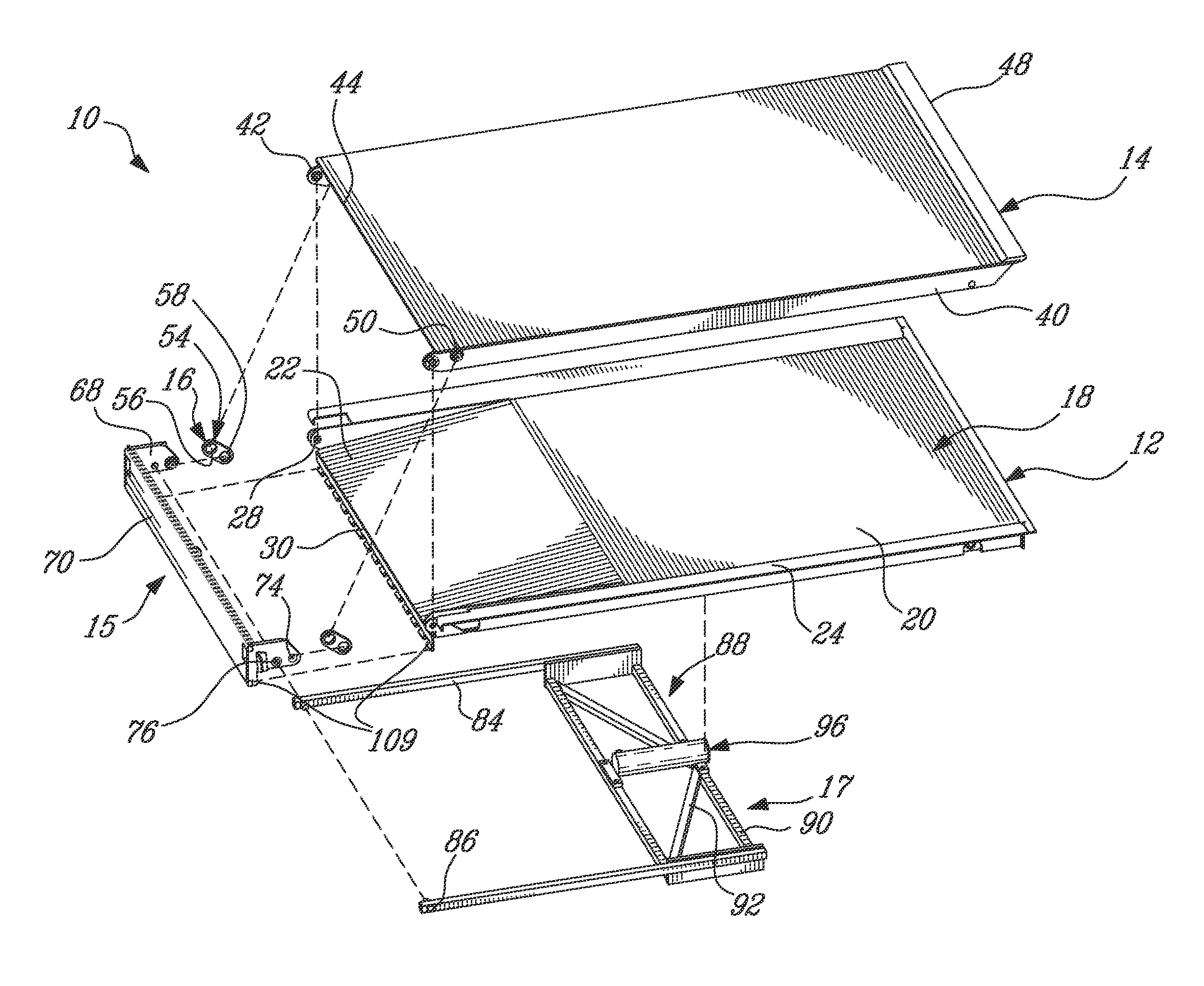
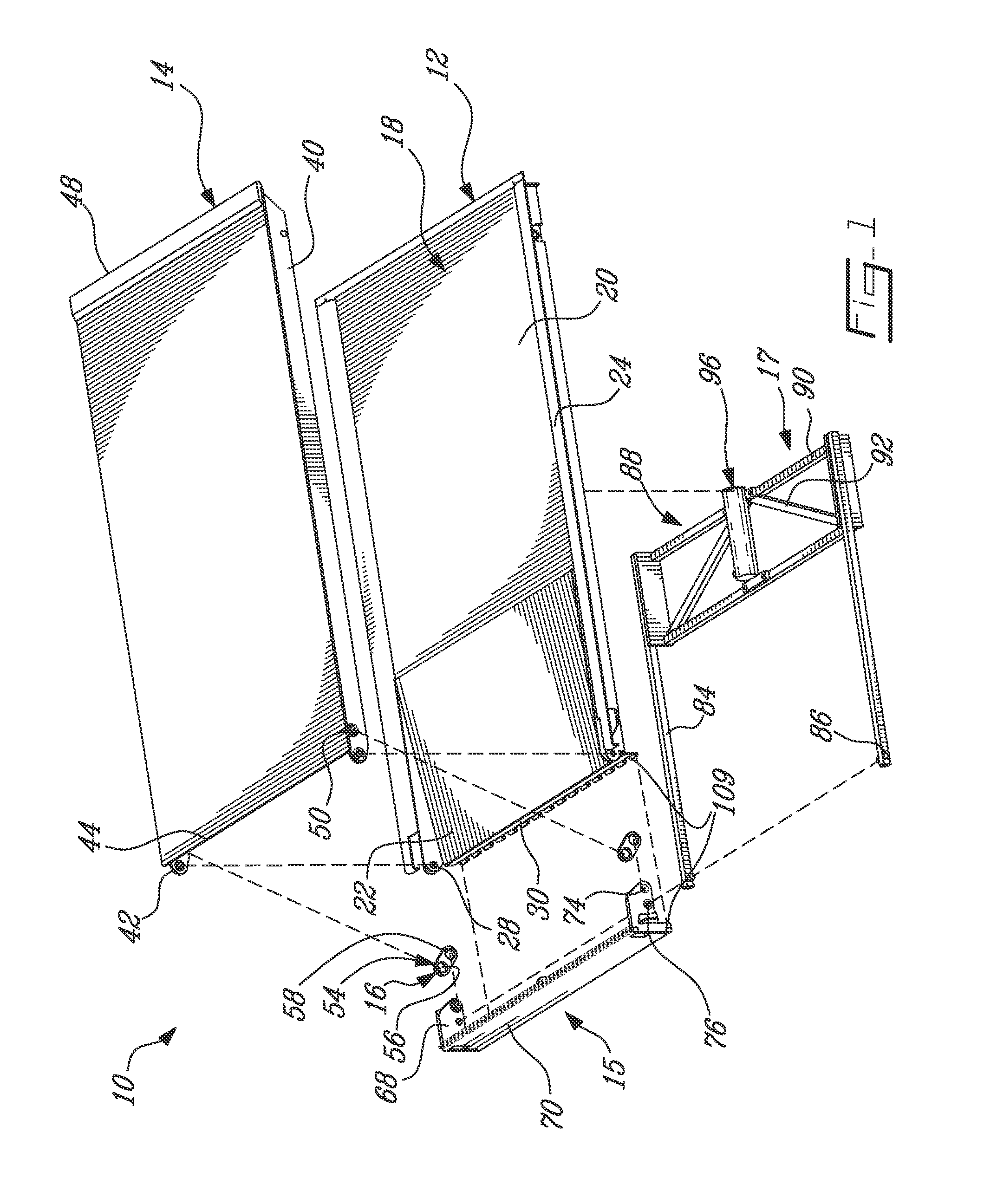
[0019]Referring to FIG. 1, a ramp assembly 10 according to an exemplary embodiment is shown. The ramp assembly 10 generally includes a fixed ramp portion 12 which is adapted to be fixed to a vehicle (e.g. bus, not shown), a pivotable ramp portion 14 pivotally connected to the fixed ramp portion 12, a cover member 15 also pivotally connected to the fixed ramp portion 12, a drive assembly 17 pivoting the cover member 15, and a multiplier assembly 16 interconnecting the cover member 15 and pivotable ramp portion 14.

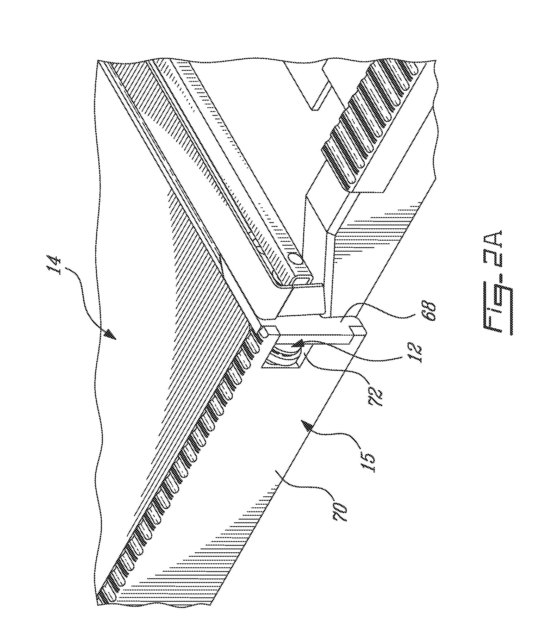
[0020]The fixed ramp portion 12 defines a ramp surface 18, which has a first part 20 intended to be leveled with a floor of the vehicle, and a second angled part 22 extending from the first part 20 in a downwardly angled manner. The fixed ramp portion 12 further includes side members 24 extending from the ramp surface 18. Referring to FIG. 2B, the side members 24 each include a side wall 26 extending upwardly from at least the angled part 22 of the ramp surface 18. Each side...


PUM


Abstract

A deployable ramp assembly including a fixed ramp portion and a pivotable ramp portion connected thereto through a direct pivot connection to pivot between stowed and deployed positions defined at a first angle from one another, a cover member pivotally connected to the fixed portion to pivot between closed and opened positions defined at a second angle from one another which is substantially smaller than the first angle, a drive assembly pivoting the cover member between the closed and opened positions, and a multiplier assembly interconnecting the pivotable portion and the cover member to transfer the pivoting motion of the cover member to the pivotable portion in an amplified manner, the multiplier assembly bringing the pivotable portion in the stowed position when the cover member is in the closed position and the pivotable portion in the deployed position when the cover member is in the opened position.

Description

TECHNICAL FIELD[0001]The present invention relates to deployable ramps for vehicles, and more particularly to such ramp assemblies having a pivotable ramp portion.BACKGROUND[0002]Deployable ramp assemblies for vehicles, for example deployable wheel chair ramps for buses, exist in a variety of configurations. Examples include ramp assemblies with a deployable portion which is slidable in and out of a space defined under a fixed ramp portion, and ramp assemblies with a pivotable portion pivoting up to more than 180° from a stowed position against the fixed portion. Typical drive mechanisms for such ramp assemblies, e.g. gear mechanisms, chain drives, belt drives, and combinations thereof, are usually relatively complex, with a number of movable parts that may become disengaged, jammed, misaligned, etc. during use.[0003]Accordingly, improvements are desirable.SUMMARY[0004]It is therefore an aim of the present invention to provide an improved deployable ramp assembly.[0005]In accordance...

Claims


Application Information

Patent Timeline
Patent Type & Authority Patents(United States)
IPC IPC(8): E01D1/00
CPCA61G3/061B65G69/2811B60P1/433A61G2003/067A61G3/067
Inventor FONTAINE, YVESMORIN, MICHEL
Owner FEDICO
Why Eureka
Try Eureka