Multiple pawl ratchet mechanism

Pending Publication Date: 2022-07-14
BUCHANAN NIGEL
View PDF5 Cites 0 Cited by
  • Summary
  • Abstract
  • Description
  • Claims
  • Application Information

AI Technical Summary

Problems solved by technology

In the drive direction the pawl as it is projected against its corresponding housing wedge shaped ramp, however the pawl teeth only truly robustly engage at or near the actual wedge shaped end contact areas, hereinafter termed engagement ramps, equivalent to approximately 40 deg. or less of the drive element teeth, the normal point of failure of most ratchets is due to over torque usage, wear or fouling of the ratchet pawl teeth, the more or larger the teeth completely engaged the less the wear or over torque problem.
As correctly illustrated in FIG. 4 U.S. Pat. No. 9,545,705 Hu when a bi-directional pawl is utilized less than half of the pawl teeth completely engage the analogous drive element teeth, furthermore this is also a similar characteristic of single direction ratchets, if the pawl and housing recess engagement ramp angles were to be modified in order to substantially improve the teeth engagement, the pawl would tend to problematically jam against the pawl recess engagement ramp, empirical testing over

Method used


Image

  • Multiple pawl ratchet mechanism
  • Multiple pawl ratchet mechanism
  • Multiple pawl ratchet mechanism

Examples


Embodiment Construction

[0045]As required, detailed embodiments of the present invention are disclosed herein; however, it is to be understood that the disclosed embodiments are merely exemplary of the invention that may be embodied in various forms. The figures are not necessarily to scale, some features may be exaggerated to show details of particular components. Therefore specific structural and functional details disclosed herein are not to be interpreted as being limiting, but merely as a basis for the claims and as one skilled in the art to variously employ the invention.

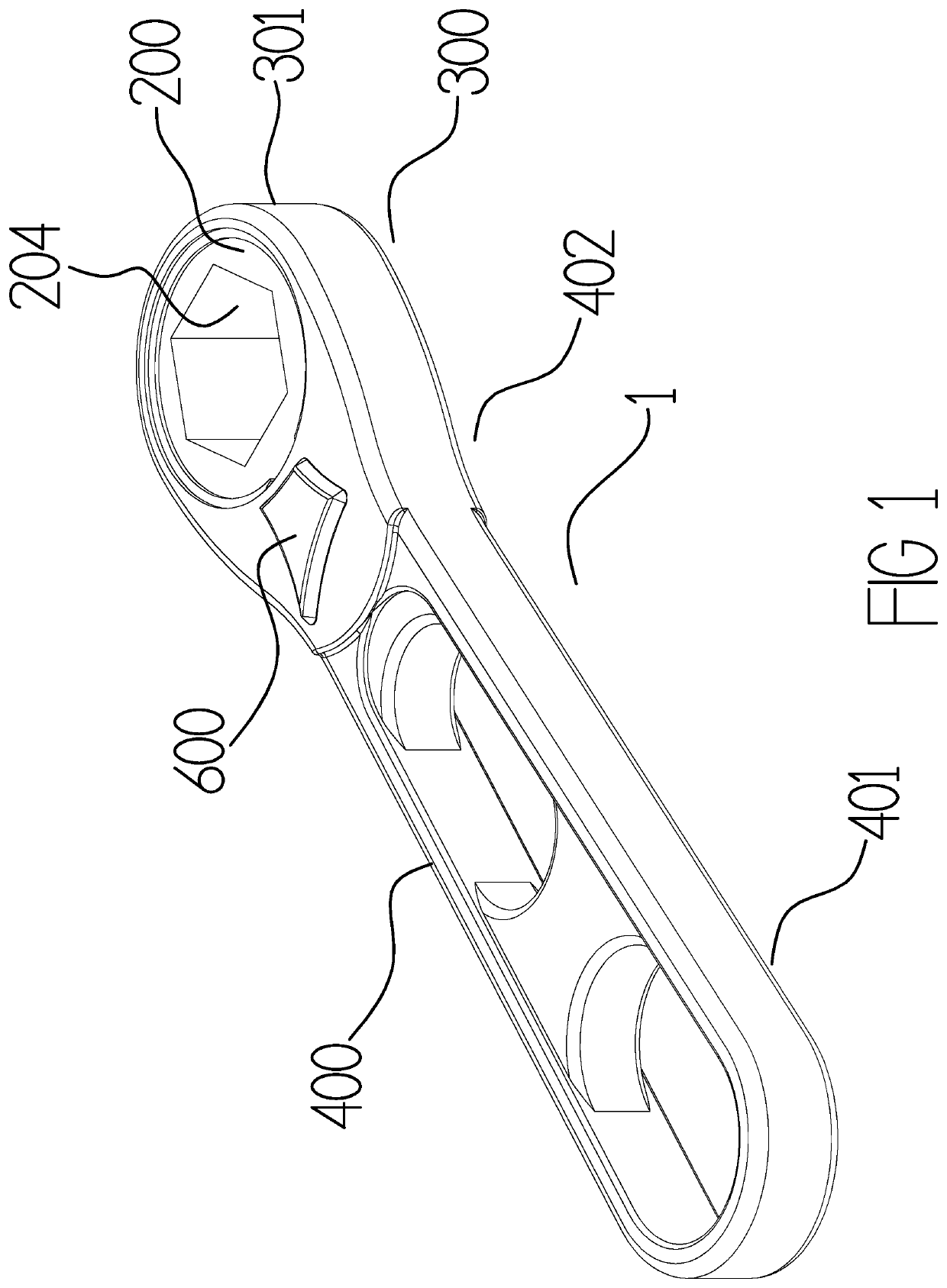
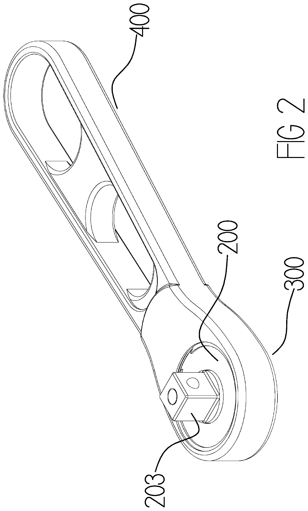
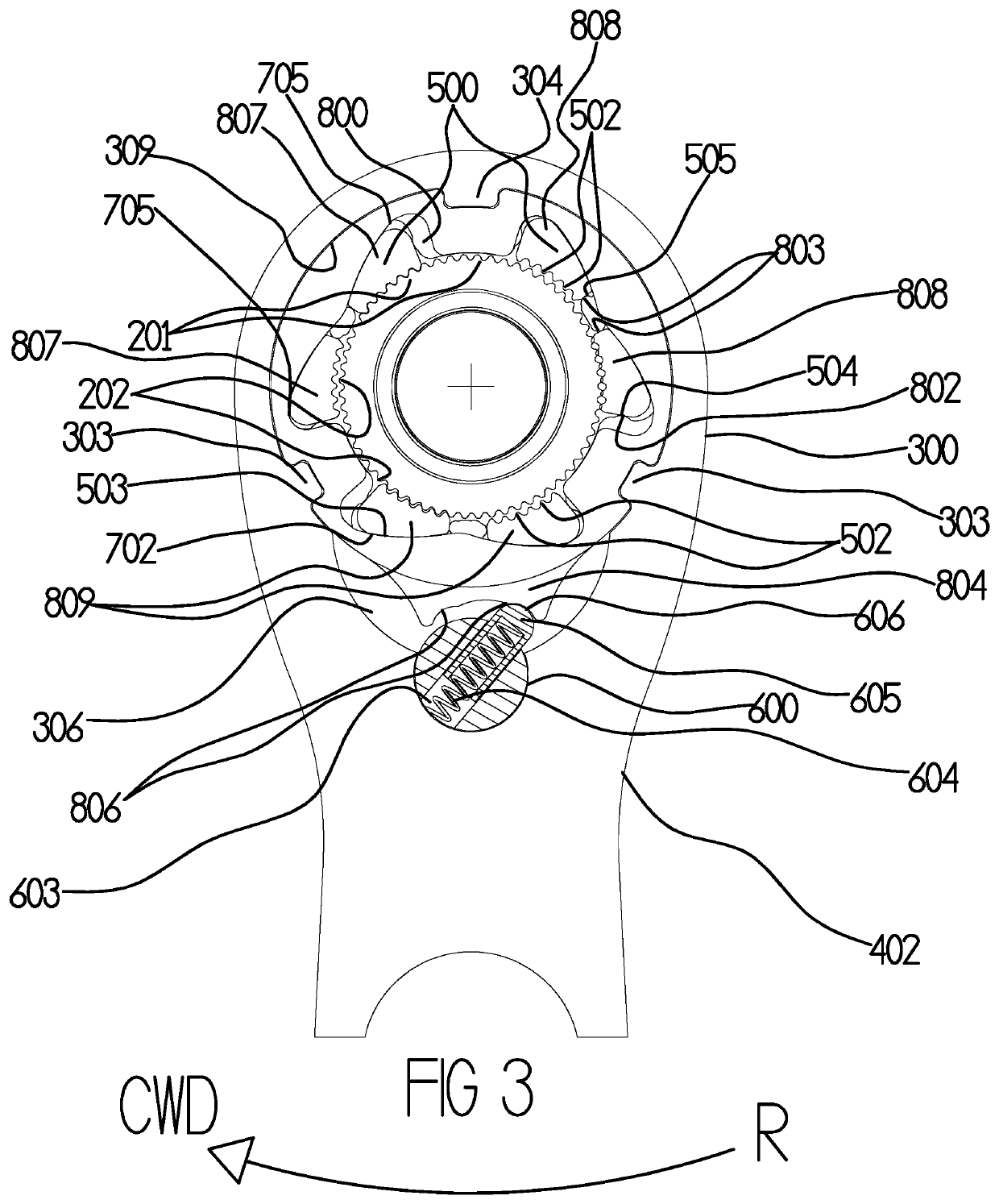
[0046]FIGS. 1-7 illustrate the embodiments of a multiple pawl ratchet mechanism 1 comprising a head portion 300 having a central chamber 309 in which a driven element 200 is received, a handle portion 400 having a levering end 401 and a levered end 402. The circular central chamber 309, the inner surface 302 of which adjoining the handle portion 402 having a further recess or connection undercut 306 for the connection to the actuatin...


PUM


Abstract

A ratchet comprises a head portion with a circular central housing having modular inserts in the form of three flat ring like layers, two outer fixed ramped profile layers engaged into housing locking profiles with a sequential actuating layer capable of limited rotation between. Opposing direction pawls are situated within the fixed layer ramped profiles. The actuating layer has engagement and disengagement profiles at either end of its pawl recesses projecting the incumbent pawls against the fixed layer ramped profiles in the chosen direction projecting them inwards locking the pawl teeth within the driven element teeth, whilst simultaneously disengaging the pawls facing the other direction. The actuating layer biasing protrusion resiliently projected in the chosen direction by a robust sprung plunger acting from within a switch bore, in the reverse direction the actuating layer resiliently rotates against said sprung plunger allowing the pawl teeth to resiliently slide over one another.

Description

CROSS REFERENCE TO RELATED APPLICATION[0001]The present application claims priority to PCT application PCT / EP2020 / 062176 filed on Apr. 30, 2020, which is a PCT application of Great Britain patent application no. 1906089.6, filed on Apr. 30, 2020.BACKGROUNDI. Field of Use[0002]The invention relates to dual direction ratchet mechanisms used in screwdrivers and wrenches (often referred to in the United Kingdom as spanners).II. Description of the Related Art[0003]Ratchet wrenches may comprise a wrench head that house a driven member. The driven member may be provided with an aperture shaped to receive an item that is to be driven. For example, the aperture may be a hexagonal aperture sized to receive a particular size of fastener head / nut. Alternatively, the driven member may comprise a spigot that projects from the wrench head to allow the wrench head to be connected to a drive socket or the like. The driven member may have a circumferentially extending surface provided with a series o...

Claims


Application Information

Patent Timeline
IPC IPC(8): B25B13/46B25B15/04
CPCB25B13/463B25B15/04
Inventor BUCHANAN, NIGEL
Owner BUCHANAN NIGEL
Why Eureka
Try Eureka