
Method of producing a stator winding for an electrical machine

a technology of stator winding and electrical machine, which is applied in the direction of electrical apparatus, dynamo-electric machines, electromagnets, etc., can solve the problems of inability to evenly cool often manufactured “unordered” windings, and inability to achieve uniform cooling of the conductor in the winding overhang

Inactive Publication Date: 2015-03-03
SEG AUTOMOTIVE GERMANY GMBH
View PDF20 Cites 7 Cited by
  • Summary
  • Abstract
  • Description
  • Claims
  • Application Information

AI Technical Summary

Benefits of technology

The present invention provides a method for producing a stator winding for an electrical machine, such as a motor vehicle. The method involves positioning a segment of the stator winding in a plane and then bending regions of the segment along folding lines to create a lap winding. This unique approach allows the segment to be easily positioned and bent to form a multi-layered structure, with fewer offsets required than a single-layer solution. The technical effect of this method is the production of a reliable and efficient stator winding for electrical machines.

Problems solved by technology

In these methods, “unordered” windings are often manufactured, for reasons of cost.
It has been shown, however, that unordered windings create loud flow noise during operation, and cooling the conductor in the winding overhang evenly is not entirely possible.
This is a very laborious process, since the individual U-shaped sections of the winding—once they have been inserted in the stator core—must be bent into position and then welded, to establish the electrical contacts.

Method used


Image

  • Method of producing a stator winding for an electrical machine
  • Method of producing a stator winding for an electrical machine
  • Method of producing a stator winding for an electrical machine

Examples


Embodiment Construction

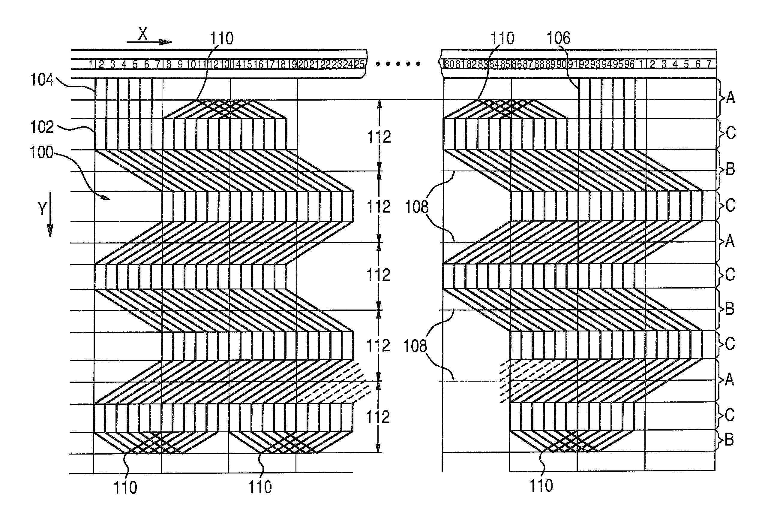
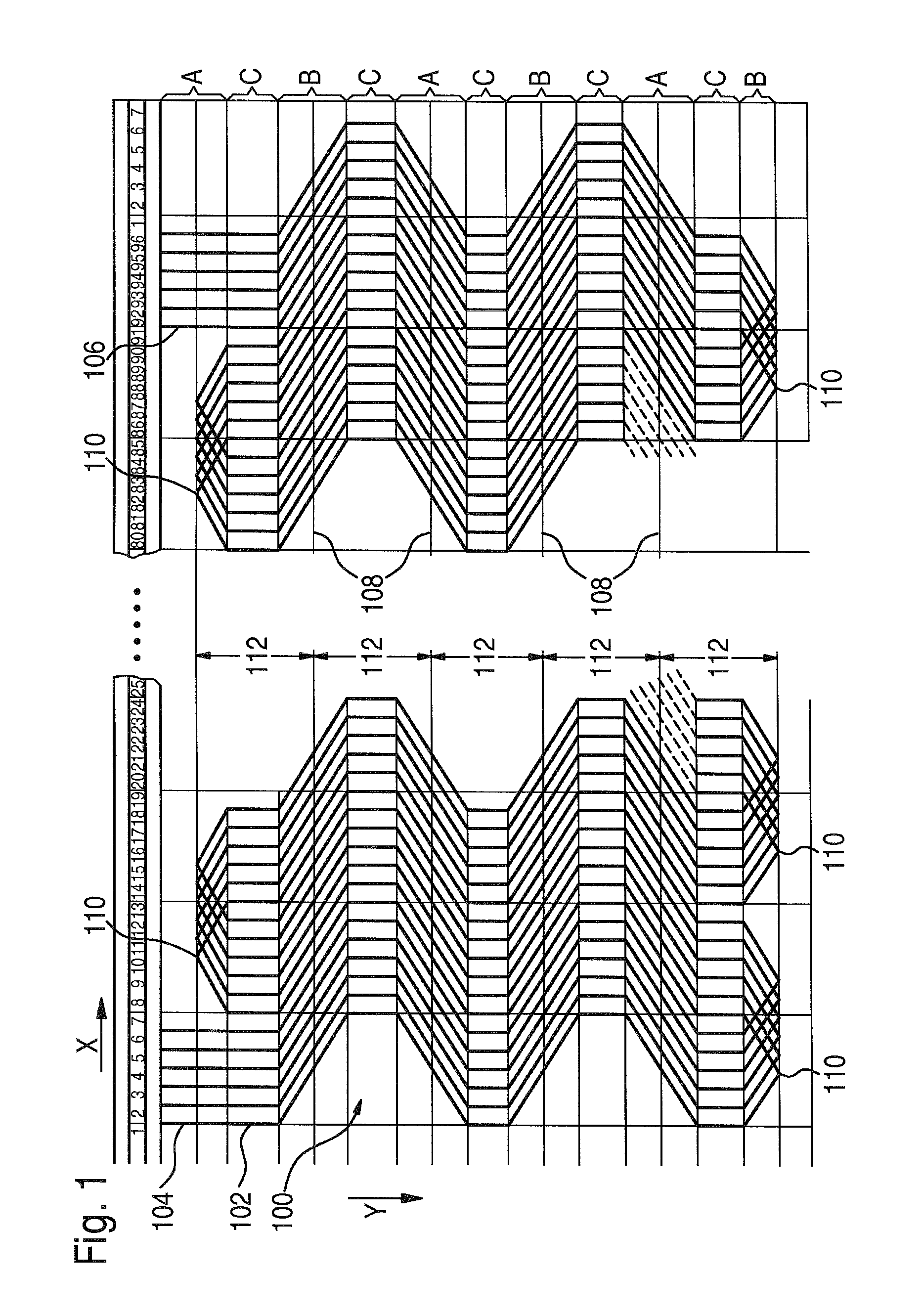
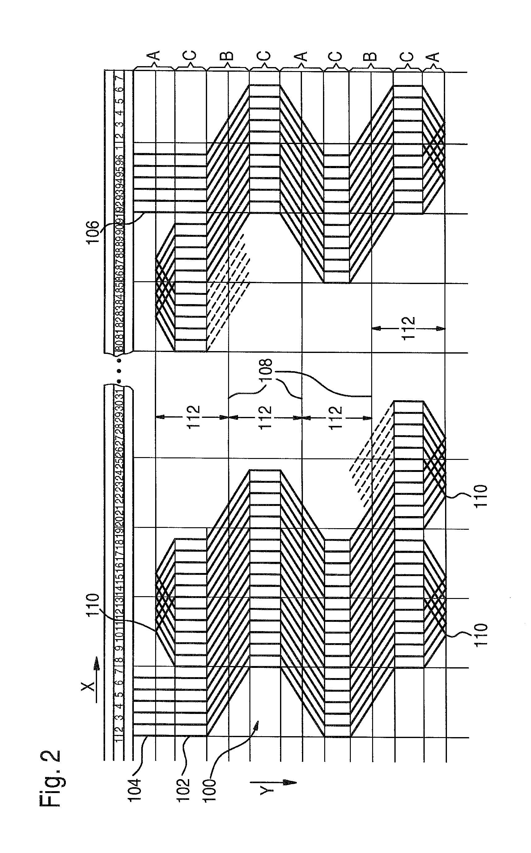
[0040]A first exemplary embodiment of a flat winding is shown in FIG. 1. This is a stator winding 100 with six phases, five conductors per slot, and 96 slots. Stator winding 100 is shown in the unfolded state in this case. To limit the illustration to the essential features, only a portion of the region between slots 19 through 84 is shown. The winding continues in the not-shown region the same as it does in the region shown. Stator winding 100 is composed of six segments. Only first segment 102, which begins with a segment start 104 in slot 1, will be discussed here. These descriptions also apply for the further segments, which start in slots 2 through 6. Segment 102 ends at segment end 106 in slot 91. Fourfold lines 108 are shown, which extend across all slots. Entire stator winding 100 extends in an XY plane that has a first direction X and a second direction Y. The slots with their ordinal numbers are plotted in increasing order in the X direction. In the Y direction, the segmen...


PUM

PropertyMeasurementUnit
diameteraaaaaaaaaa
shapeaaaaaaaaaa
lengthsaaaaaaaaaa

Abstract

A method of producing a stator winding for a stator of an electrical machine includes positioning a phase winding segment of the stator winding in a same plane in a serpentine manner in a first direction (X) and in a shape of a wave in a second direction (Y) transverse to the first direction. The method includes bending regions (A, B, C) of the phase winding segment toward one another along a folding line to form a lap winding including positioning regions (C) parallel to each other connected by regions (B) where the regions (B) cross the at least one folding line (108). The phase winding is formed with a continuous wire.

Description

CROSS-REFERENCE TO A RELATED APPLICATION[0001]The invention described and claimed hereinbelow is also described in German Patent Application DE 10 2005 054 863.6 filed on Nov. 21, 2005. This German Patent Application, whose subject matter is incorporated here by reference, provides the basis for a claim of priority of invention under 35 U.S.C. 119 (a)-(d).BACKGROUND OF THE INVENTION[0002]Methods for manufacturing a stator winding for a stator of an electrical machine are known from the related art. In these methods, “unordered” windings are often manufactured, for reasons of cost. With this type of winding, it is possible to only approximate the subsequent position of the conductor in advance, since the stator winding is often wound onto winding stars, and the winding stars that are produced are then drawn into the stator. Since the configuration and shape, in particular, of the conductor in the winding overhang are not easily influenced, this type of winding is also referred to as ...

Claims


Application Information

Patent Timeline
Patent Type & Authority Patents(United States)
IPC IPC(8): H02K15/00H02K3/12H02K3/24H02K15/04
CPCH02K15/0414H02K3/12H02K3/24H02K15/0478Y10T29/49009Y10T29/49011Y10T29/49012Y10T29/49073
Inventor WOLF, GERTBERGER, THOMAS
Owner SEG AUTOMOTIVE GERMANY GMBH
Learn More