
Novel stamping robot

A robot and a new type of technology, applied in metal processing equipment, feeding devices, safety equipment, etc., can solve problems such as unsafety, work-related accidents, and handicapping due to broken hands, so as to achieve less material consumption, reduce consumable materials, and improve safety. Effect

Inactive Publication Date: 2017-01-11
佛山市顺德区天本模具制造有限公司
View PDF9 Cites 2 Cited by
  • Summary
  • Abstract
  • Description
  • Claims
  • Application Information

AI Technical Summary

Problems solved by technology

[0002] The current punching equipment is generally operated manually when stamping parts, that is, manually put the workpiece on the mold of the punching machine. It is very unsafe to place and take out workpieces by hand. Work-related accidents often occur, causing people to be crushed and disabled.

Method used


Image

  • Novel stamping robot

Examples


specific Embodiment approach

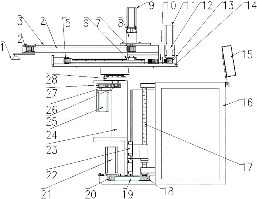
[0014] figure 1 Show the specific embodiment of a kind of novel stamping robot of the present invention: a kind of novel stamping robot, comprise fuselage main body 16 and the arm main body 3 above fuselage main body 16, wherein said fuselage main body 16 is provided with controller 15, controls Device 15 links to each other with fuselage main body 16, and one side of fuselage main body 16 is provided with elevating mechanism, and elevating mechanism comprises fuselage motor 21, fuselage screw rod 17 and fuselage linear guide 22, wherein fuselage screw rod 17 is fixed on fuselage main body On the outer side wall of 16, the bottom of fuselage motor 21 and fuselage screw rod 17 passes through fuselage main synchronous wheel 20, fuselage from synchronous wheel 18, and the mechanism between fuselage main synchronous wheel 20 and fuselage from synchronous wheel 18 The body timing belt 19 is connected, wherein the body motor 21 is connected with the main synchronous wheel 20 of the ...


PUM


Abstract

The invention discloses a novel stamping robot and relates to the field of automatic machines. The novel stamping robot comprises a robot body and an arm body above the robot body. The robot body is provided with a controller. A lifting mechanism is arranged on one side of the robot body. The lifting mechanism is fixed to the rear side wall of the robot body. A rotating mechanism is arranged on the lifting mechanism. A front-back telescopic mechanism is arranged above the rotating mechanism and is provided with a workpiece correcting mechanism. A suction cup is arranged below the workpiece correcting mechanism. The robot is suitable for stamping equipment, safety can be improved, in addition, the rotation angle can reach 360 degrees, and therefore stamping is more convenient. The robot is mainly composed of the rotating mechanism, the lifting mechanism, the front-back telescopic mechanism and the workpiece correcting mechanism; the rotating inertia of the robot during rotation is small, so that the requirement for the equipment strength of the robot is greatly lowered, material consumption is less, stability is higher, the requirement for the rated power of a motor is lowered, and energy can be effectively saved.

Description

technical field [0001] The invention relates to the field of automatic machinery, in particular to a novel stamping robot. Background technique [0002] The current punching equipment is generally operated manually when stamping parts, that is, manually put the workpiece on the mold of the punching machine. It is very unsafe to place and take out workpieces by hand. Work-related accidents often occur, causing people to be crushed and disabled. The application number is 201010259992.1. The punch press intelligent manipulator adopts a servo system to speed up the operation of the machine, save electricity, and achieve energy saving and environmental protection. In the present invention, the lifting mechanism part is arranged under the rotating mechanism, so that the moment of inertia of the equipment rotation is small, and the overall operation of the equipment is stable. Contents of the invention [0003] In view of the deficiencies of the prior art, the purpose of the pr...

Claims


Application Information

Patent Timeline
IPC IPC(8): B21D43/18B21D55/00
CPCB21D43/18B21D55/00
Inventor 郭锦泉
Owner 佛山市顺德区天本模具制造有限公司
Learn More