Apparatus for rivetting

a technology of riveting apparatus and riveting head, which is applied in the direction of screwdrivers, threaded fasteners, manufacturing tools, etc., can solve the problems of insufficient formation of the end of the rivet b>1/b> into the shape of the head, long time to finish the riveting operation, and the conventional riveting apparatus. achieve the effect of improving the quality of the riveting operation, reducing the time of heating and cooling, and improving the quality of the riveting

Active Publication Date: 2012-12-11
GUNYANG ITT
View PDF20 Cites 378 Cited by
  • Summary
  • Abstract
  • Description
  • Claims
  • Application Information

AI Technical Summary

Benefits of technology

[0017]Accordingly, the present invention has been made in an effort to solve the problems occurring in the related art, and an object of the present invention is to provide a riveting apparatus which can improve upon the quality of a riveting operation, increase energy efficiency, shorten the time required for riveting, and improve productivity.
[0018]Another object of the present invention is to provide a riveting apparatus which has a simple construction and can be easily fabricated at small cost.
[0024]According to a still further aspect of the present invention, at least one stripper is coupled to an outer surface of the guide to project beyond the lower end of the guide so that the lower end can be prevented from being brought into direct contact with a surface of a plate member.
[0025]Thanks to the above features of the present invention, advantages are provided in that, since a riveting operation is implemented such that hot air is supplied and is passed through discharge holes defined in a forming tool to heat a rivet and then an end of the rivet is formed into the shape of a head, the quality of the riveting operation can be improved upon, energy efficiency can be increased, and heating and cooling times can be shortened, whereby productivity can be improved.
[0026]Further, because the riveting apparatus has a simple construction, it can be easily fabricated at small cost, whereby economic viability can be ensured.

Problems solved by technology

However, the conventional riveting apparatus suffers from drawbacks because, since the heating and the application of pressure are simultaneously implemented, pressure is likely to be applied when the end of the rivet 1 is not completely melted, and thereby, the end of the rivet 1 is likely to be inadequately formed into the shape of a head.
Further, because the temperature of the forming tool 14 slowly decreases upon cooling, it takes a long time to finish the riveting operation.
Nevertheless, this conventional riveting apparatus has a drawback in that, since a driving unit for lowering and raising the hot air supply unit 22 and a driving unit for lowering and raising the forming tool 24 should be separately provided, the construction of the riveting apparatus becomes complicated and the fabrication cost of the riveting apparatus increases.
Nonetheless, the conventional riveting apparatus encounters a problem in that, because the size of the housing which surrounds the forming tool 34 and the heater 32 can not be increased beyond a certain size limit, the size of the heater 32 disposed in the housing is restricted and the amount of hot air for heating the end of the rivet 1 is limited, whereby a time required for melting the end of the rivet 1 can not but be extended.

Method used


Image

  • Apparatus for rivetting
  • Apparatus for rivetting
  • Apparatus for rivetting

Examples


Embodiment Construction

[0035]Hereafter, a riveting apparatus in accordance with an embodiment of the present invention will be described in detail with reference to the accompanying drawings.

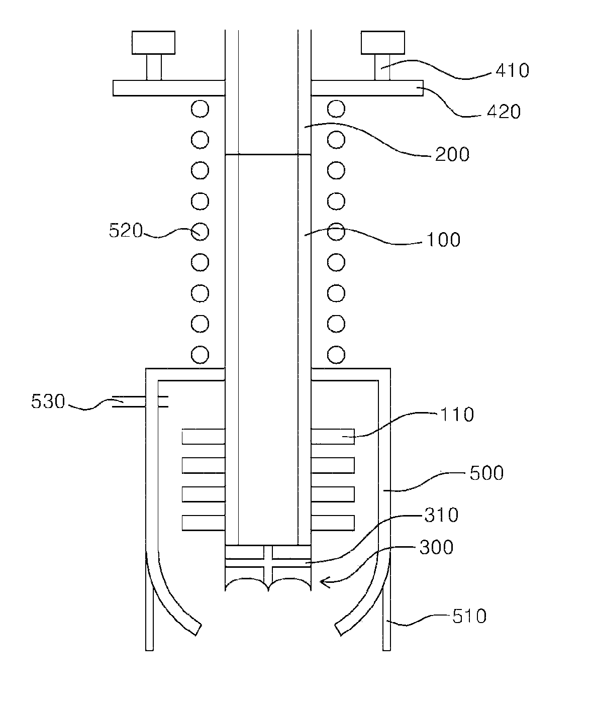
[0036]FIG. 4 is a sectional view illustrating a forming tool and other component parts of a riveting apparatus in accordance with an embodiment of the present invention.

[0037]Referring to FIG. 4, the riveting apparatus according to the present invention generally includes a hot air pipe 200, a connection pipe 100, a forming tool 300, a moving unit, and a guide 500.

[0038]First, the hot air pipe 200 will be described. The hot air pipe 200 has the shape of a hollow tube and defines a path through which hot air flows.

[0039]The connection pipe 100 also has the shape of a hollow tube, is coupled to the lower end of the hot air pipe 200, and defines a path through which hot air having passed through the hot air pipe 200 flows.

[0040]In order to promote heat transfer, the connection pipe 100 is made of a metallic material such...


PUM

PropertyMeasurementUnit
shapeaaaaaaaaaa
elastic forceaaaaaaaaaa
pressureaaaaaaaaaa

Abstract

A riveting apparatus includes a hot air pipe; a connection pipe coupled to the hot air pipe; a forming tool having a configuration in which peripheral and center portions project downward and portions existing therebetween are curved upward, defined with discharge holes which extend in axial and radial directions, and coupled to a lower end of the connection pipe so that hot air having passed through the connection pipe can be discharged through the discharge holes to heat an end of a rivet to thereby allow the forming tool to form the end of the rivet into the shape of a head; a moving unit coupled to the hot air pipe or the connection pipe to move the forming tool upward and downward; and a guide surrounding the forming tool so that hot air discharged through the discharge holes can be directed toward the end of the rivet.

Description

REFERENCE TO RELATED APPLICATIONS[0001]This a continuation of pending International Patent Application PCT / KR2008 / 006511 filed on Nov. 5, 2008, which designates the United States and claims priority of Korean Patent Applications No. 10-2007-0112060 filed on Nov. 5, 2007, the entire contents of which are incorporated herein by reference.FIELD OF THE INVENTION[0002]The present invention relates to a riveting apparatus, and more particularly, to a riveting apparatus wherein a riveting operation is implemented in a manner such that hot air is discharged through discharge holes defined through a forming tool in axial and radial directions to melt an end of a rivet, the forming tool is then lowered to apply pressure to the end of the rivet and form the end of the rivet into the shape of a head, and cooling air is supplied to the forming tool and a connection pipe connected to the upper end of the forming tool to decrease the temperature of the forming tool and thereby cool the end of the ...

Claims


Application Information

Patent Timeline
Patent Type & Authority Patents(United States)
IPC IPC(8): B23P11/00B29C35/02B29C65/02B21K1/58B21K1/44
CPCB21J5/00B29C65/18B29C65/26B29C65/601B29C65/602B29C65/72B29C66/0342B29C66/1122B29C66/348B29C66/3494B29C66/43B29C66/81423B29C66/81429B29C66/81431B29C66/81812B29C66/8227B29C66/8242B29C66/8322F16B19/12B29C66/81811B29C65/10Y10T29/53774B29C65/30B29C66/21B29C65/00F16B19/00
Inventor KIM, TAEK-HYUN
Owner GUNYANG ITT
Why Eureka
Try Eureka