
Mechanical quantity sensor and method of manufacturing the same

a technology of mechanical quantity sensor and manufacturing method, which is applied in the direction of acceleration measurement using interia force, turn-sensitive devices, instruments, etc., can solve the problem of not always easy to prepare semiconductor substrates having suitable thicknesses, and achieve the effect of improving the freedom of choice of the thickness of semiconductor substrates

Inactive Publication Date: 2012-12-11
DAI NIPPON PRINTING CO LTD
View PDF12 Cites 3 Cited by
  • Summary
  • Abstract
  • Description
  • Claims
  • Application Information

AI Technical Summary

Benefits of technology

The present invention provides a mechanical quantity sensor and a method of manufacturing it that improves the freedom of choice of the thickness of a semiconductor substrate to be prepared. This is achieved by integrating a first structure and a second structure, with a connection portion connecting them, and adjusting the thickness of a third layer of the semiconductor substrate in which the first structure is made. This allows for flexibility in the design of the mechanical quantity sensor, making it easier to manufacture and modify.

Problems solved by technology

It is not always easy to prepare semiconductor substrates having suitable thicknesses corresponding to the respective specifications.

Method used


Image

  • Mechanical quantity sensor and method of manufacturing the same
  • Mechanical quantity sensor and method of manufacturing the same
  • Mechanical quantity sensor and method of manufacturing the same

Examples


first embodiment

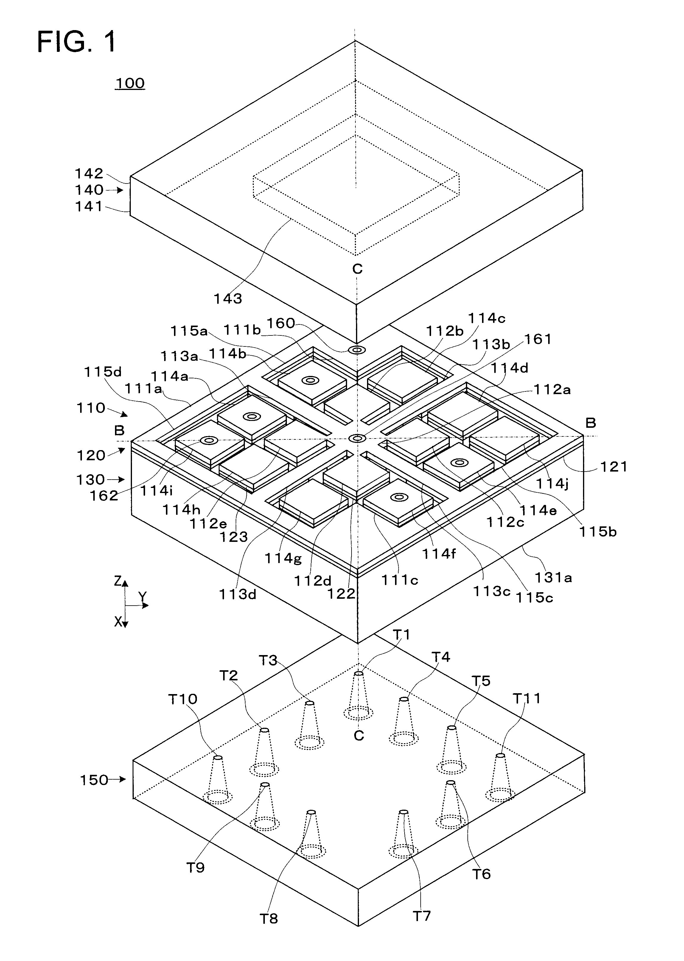
[0035]FIG. 1 is an exploded perspective view showing a state that a mechanical quantity sensor 100 is disassembled. The mechanical quantity sensor 100 has a first structure 110, a joining part 120, and a second structure 130 which are stacked one another, and a first base 140 and a second base 150.

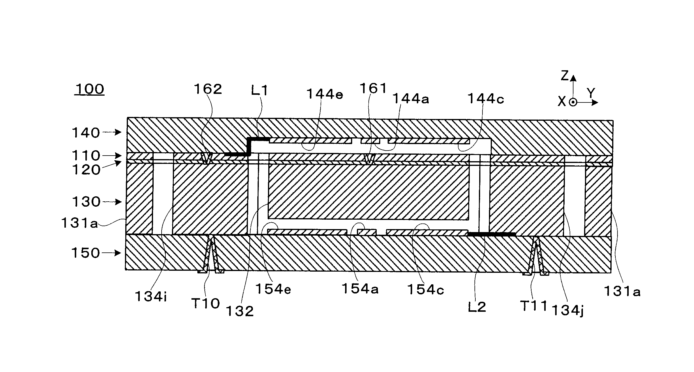
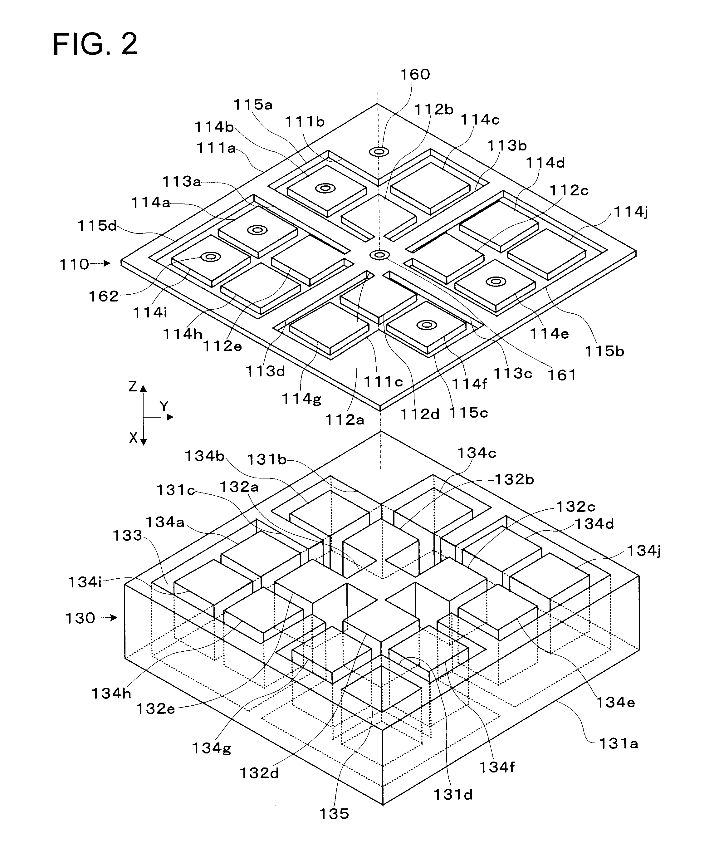
[0036]FIG. 2 is an exploded perspective view showing a state that part (first structure 110 and second structure 130) of the mechanical quantity sensor 100 is further disassembled. FIGS. 3, 4, 5 are top views of the first structure 110, the joining part 120, and the second structure 130, respectively. FIG. 6, FIG. 7, FIG. 8 are a bottom view of the first base 140, a top view of the second base 150, and a bottom view of the second base 150, respectively. FIG. 9 and FIG. 10 are cross-sectional views of the mechanical quantity sensor 100 taken along a line B-B and a line C-C of FIG. 1.

[0037]The mechanical quantity sensor 100 functions by itself or in combination with a circuit board (for exam...

second embodiment

[0189]FIG. 14 is a partial cross-sectional view showing a main part of a mechanical quantity sensor 200 according to a second embodiment of the present invention. Parts common to FIG. 10 are given the same reference numerals, and overlapping description is omitted.

[0190]As shown in FIG. 14, the mechanical quantity sensor 200 of this embodiment is different from the mechanical quantity sensor 100 of the first embodiment in method of adjusting (and as its consequence the thickness of) the second structure (second structures 130, 230). Specifically, the mechanical quantity sensor 100 of the first embodiment has the second structure 130 which is adjusted to be smaller in thickness after the first base 140 and the first structure 110 are joined and before the second base 150 and the second structure 130 are joined. In comparison, the mechanical quantity sensor 200 of this embodiment has a second structure 230 which is adjusted to be larger in thickness after a first base 140 and a first ...


PUM

PropertyMeasurementUnit
thicknessaaaaaaaaaa
heightsaaaaaaaaaa
heightsaaaaaaaaaa

Abstract

A mechanical quantity sensor includes a first structure having a fixed portion with an opening, a displaceable portion arranged in the opening and displaceable relative to the fixed portion, and a connection portion connecting the fixed portion and the displaceable portion, a second structure having a weight portion joined to the displaceable portion and a pedestal arranged surrounding the weight portion and joined to the fixed portion, the second structure being arranged and stacked on the first structure, a first base connected to the fixed portion and arranged and stacked on the first structure, and a second base connected to the pedestal and arranged and stacked on the second structure. The weight portion is adjusted in thickness after the first structure is made and before the second base and the second structure are joined.

Description

TECHNICAL FIELD[0001]The present invention relates to a mechanical quantity sensor detecting a mechanical quantity and a method of manufacturing the same.BACKGROUND ART[0002]There has been disclosed a technique of a mechanical quantity sensor, which is structured such that a transducer structure formed of a semiconductor is sandwiched by a pair of glass substrate and joined thereto, for detecting an acceleration and an angular velocity (see Patent Reference 1).[0003]Patent Reference 1: JP-A 2002-350138 (KOKAI)DISCLOSURE OF THE INVENTION[0004]Generally, it is known that mechanical properties (resonance frequency, spring constant, and the like) of a mechanical quantity sensor depend on shapes and sizes of a weight (weight portion) and a beam (connection portion), and the like. Accordingly, designing of the mechanical quantity sensor satisfying a specification of desired mechanical properties is performed normally by presuming outer shape dimensions and a thickness of the beam, a thick...

Claims


Application Information

Patent Timeline
Patent Type & Authority Patents(United States)
IPC IPC(8): H01L21/00G01C19/56G01P15/18
CPCB81C1/00714G01C19/56G01P15/097G01P15/125G01P15/18G01P15/0802B81B2201/0235B81B2201/0242Y10T29/49002
Inventor TAKESHITA, KIYOKAZUAIDA, KAZUHIKO
Owner DAI NIPPON PRINTING CO LTD
Learn More