Often times, there will also be a
clutter of various sizes and ages of brushes, frequently stiffened by old paint that was never completely cleaned from the
brush prior to storage.
While this approach has been used for a very long time, and is extremely commonplace in the vast majority of homes, the paint can and
brush techniques have suffered from a number of undesirable shortcomings.
Unfortunately, the paint stored in ordinary paint cans has a relatively limited
shelf life.
The air gap present above the liquid paint acts as a large source of
oxygen, which invariably leads to a degradation of the paint.
Typically, at least the
surface layer of the paint will harden and be unsuitable.
The amount of paint which is lost to this process is frequently dependent upon some complex combination of how full the paint can is, the ingredients of the paint, and how long the can is stored.
Consequently, the homeowner will never know quite what to expect when the can is opened, even only a few months later.
Worse, even if there is still some
usable paint in the can, it is well-known that the pigments that are contained in most paints are more dense than the base.
Consequently, when the homeowner strips the hardened surface off of the paint and then mixes the remaining
usable paint in the ordinary manner, the concentration of pigments has unintentionally been increased, potentially affecting the match between the original paint and the paint now remaining in the can.
Not only is paint difficult to store in ordinary paint cans and buckets, but used brushes are equally difficult to store.
Unfortunately, the very characteristic which makes a brush more desirable for the application of paint also makes the brush somewhat more difficult to clean.
Removal of this paint can be difficult.
But, in addition to getting the dried paint off, there will also be a large amount of unused paint retained within the brush.
Even with a fairly rigorous cleaning, the brush will almost always still have some paint remaining, and over time and with more use, the brush will harden up and become useless.
In the end, a diligent person will spend a great deal of time and cleaner cleaning up a high quality brush, only to still eventually throw the expensive brush away.
Another drawback with the traditional tools and methods of paint application is in the control of the amount of paint applied, and control over the
surface finish.
However, this thicker paint invariably leads to the creation of a pattern of brush strokes that will remain even after the paint is dried.
While brush strokes are desired in some instances to add texture, the painter rarely can control this, since thin paints will run and drip, and thicker paints retain the
brush stroke.
Otherwise, all too commonly there will be an occasional “streak” where the paint was either applied too thinly or not applied at all.
As will also be apparent, the application of thicker paint also results in the consumption of a relatively large amount of paint.
Unfortunately, with a brush there is little control available.
Yet another drawback comes when a non-traditional surface is to be painted.
Again, with a brush there is little control available.
Further compounding the problem is the knowledge that, when it comes to non-traditional surfaces, many of these more modern tools that are used to apply coats of paint are unsuited to these non-traditional surfaces.
While improved can seals and geometries have also been developed, these fail to resolve the problems of long term storage within a paint can.
Unfortunately, these commercial sprayers are generally quite expensive, often require special knowledge and training to operate, require more care to clean and store than an ordinary homeowner will provide, and require storage space that is already scarce in most homes.
Consequently, few homeowners would consider investing in a commercial
sprayer.
Finally, these commercial paint sprayers rely upon cans or pails of paint which present the same problems with storage and aging as already described herein above.
Then the spray cap is replaced, and the can may be stored for great lengths of time.
However, these spray cans differ from the commercial sprayers in several important and undesirable ways.
Spray cans are practically limited to operation in either an on or off mode, and the user cannot readily control or vary the amount of spray discharged.
In addition, and as an undesirable side-effect of the ease of use of a spray can, when a child gains access to the can much harm may be done.
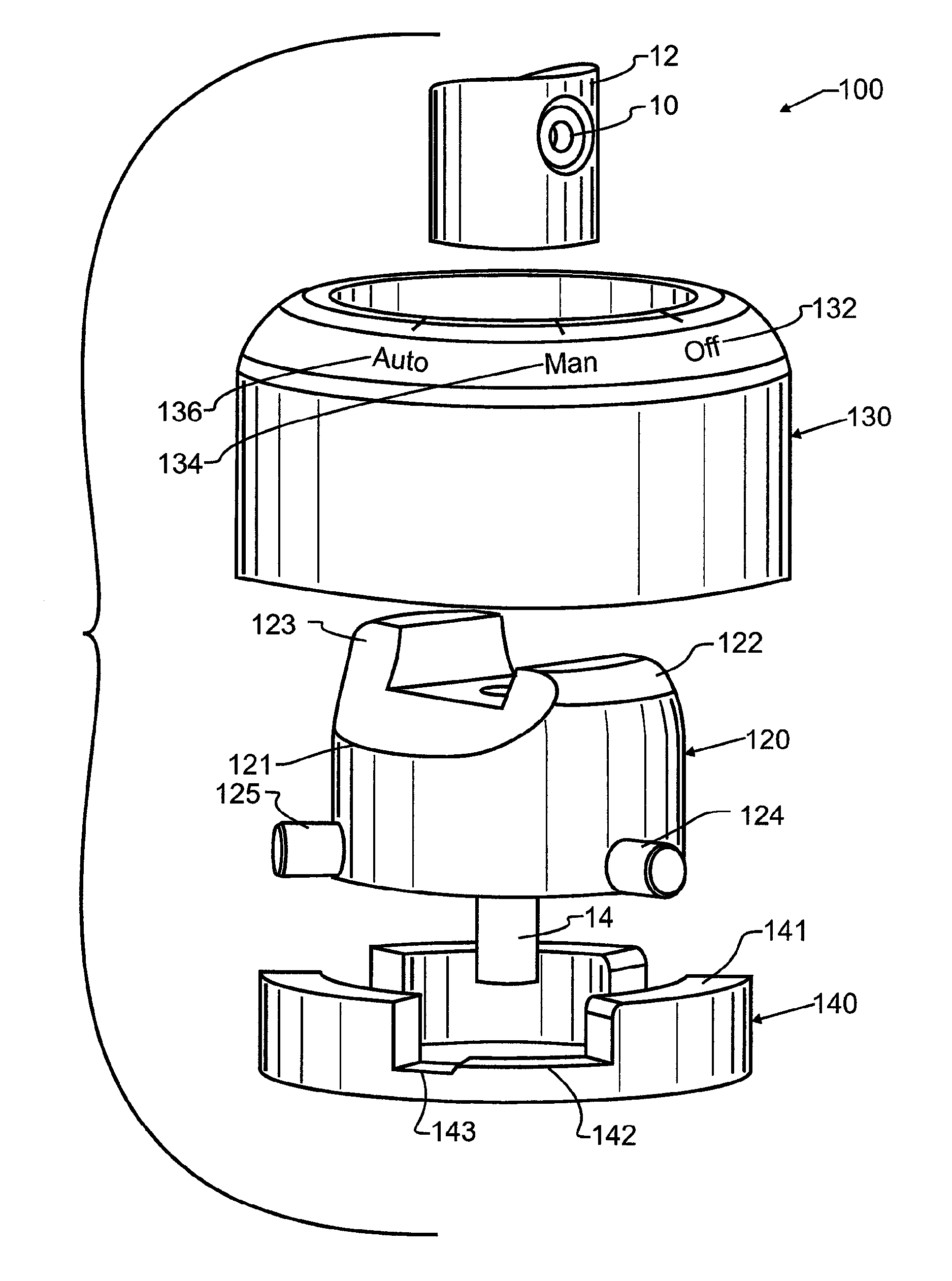
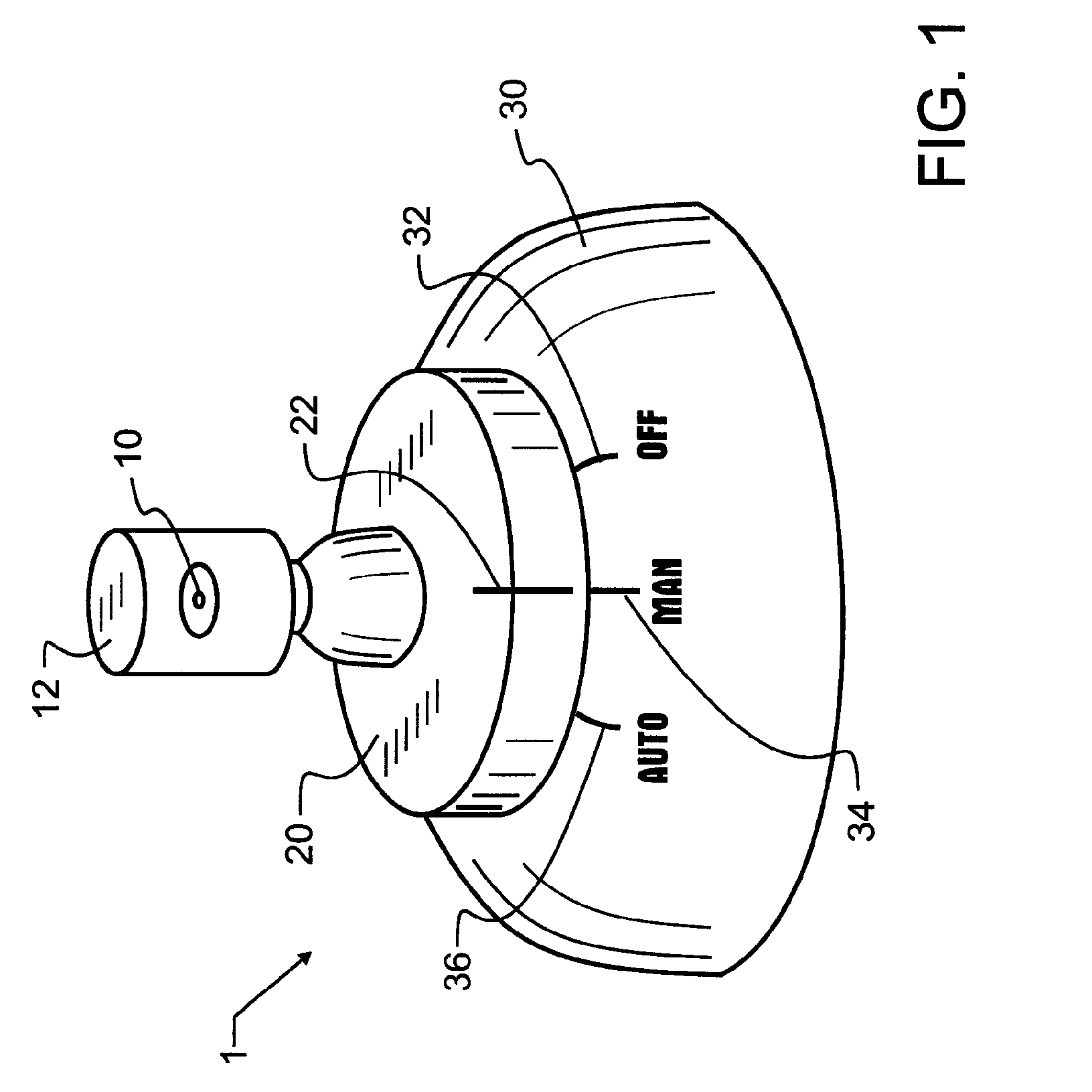
It does not, however, disclose the concept of a floating index, a pin guided track for spray selection, and it will not work with modern spray cans.
While the caps illustrated therein provide adjustable spray settings, the cap is not durable, owing to the geometries of construction, and will become contaminated with paint on the top surface due to splatter and the like.
Finally, since the interior and exterior sections must rotate relative to each other and there is no manual access to the interior section, the cap is not readily manually adjusted and there will be a tendency for the interior and exterior to rotate together.
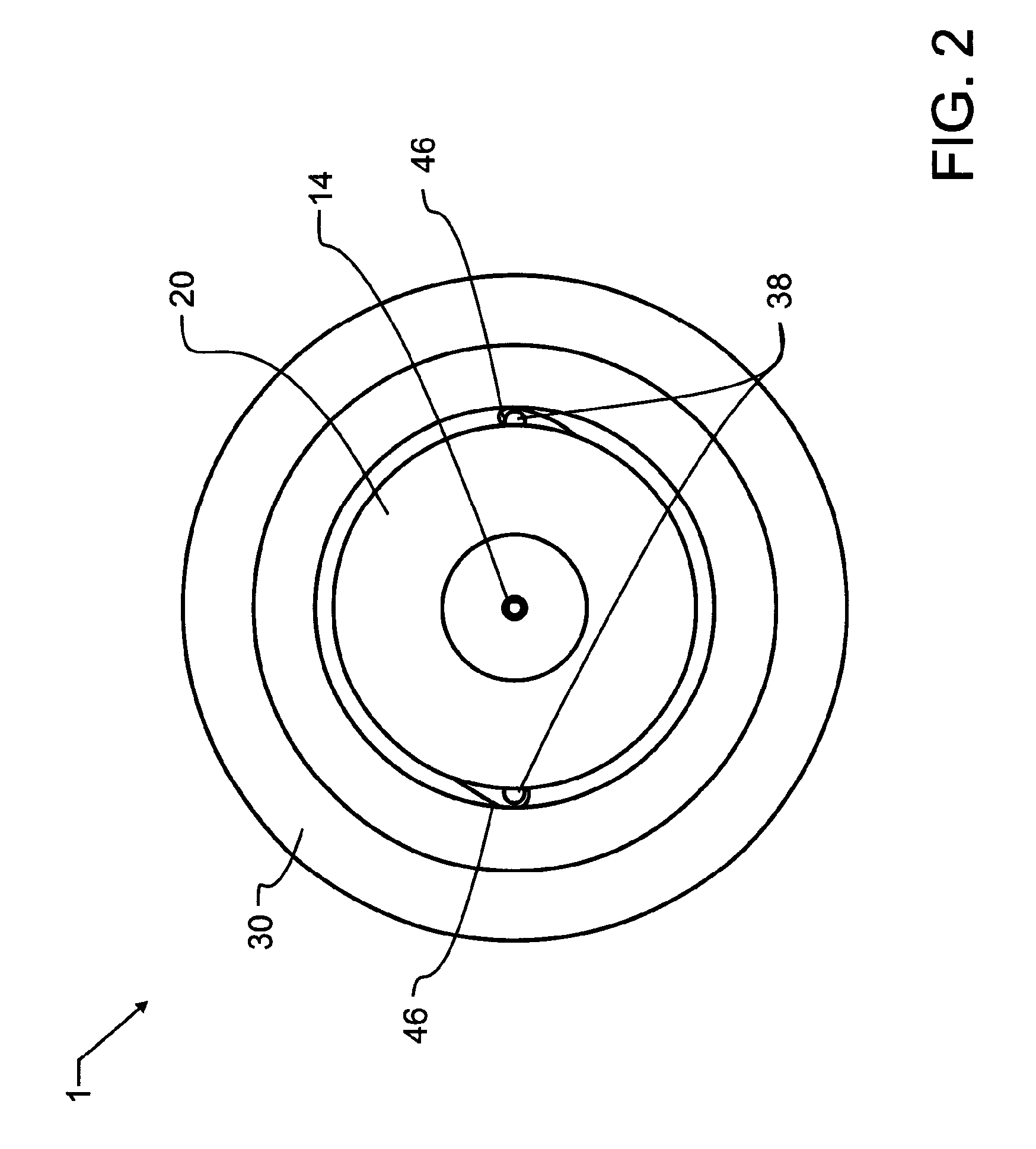
The track is useful for controlling the amount of product being dispensed, but fails to provide any
accommodation for factory or aftermarket misalignment.
Unfortunately, the Jones invention does not balance the can well, leading to significant operator fatigue.
Further, the Jones invention does not readily store directly with the spray can, mandating either repeated
assembly and disassembly from a spray can or causing substantial interference with the storage and access of individual spray cans.
In
spite of the substantial consideration and development that has occurred through the years, these patents are deficient in being capable of adequate operation with modern spray cans, in occupying minimal space, in functioning with the simplicity of a standard spray can, and in other manners that will become apparent.

