Liquid application apparatus, liquid application method and image forming apparatus

a technology of liquid application apparatus and liquid application method, which is applied in the direction of measuring apparatus components, instruments, coatings, etc., can solve problems such as prone to application failure, and achieve the effects of improving application stability performance, drying and leakage of remaining liquid, and preventing leakag

Inactive Publication Date: 2012-12-18
FUJIFILM CORP
View PDF10 Cites 5 Cited by
  • Summary
  • Abstract
  • Description
  • Claims
  • Application Information

AI Technical Summary

Benefits of technology

[0014]The present invention has been contrived in view of these circumstances, an object thereof being to provide a liquid application apparatus, a liquid application method and an image forming apparatus which can fix failures caused by air bubbles or remaining liquid in a liquid holding space in order to improve the application stability.
[0016]According to this aspect of the invention, by arranging the recovery port above the supply port in terms of the vertical direction, air bubbles included in the liquid holding space can be discharged via the recovery port. Further, by arranging the recovery port below the supply port in terms of the vertical direction, the liquid in the liquid holding space can be recovered via the recovery port. In other words, by arranging the recovery port and the supply port in different positions in terms of the vertical direction, it is possible to discharge air bubbles included in the liquid holding space and to recover the liquid in the liquid holding space. As a result, application failures due to the air bubbles, and drying and leakage of the remaining liquid, can be prevented, thereby improving the application stability performance with respect to a recording medium.
[0031]According to this aspect of the invention, the accuracy of the application volume of the treatment liquid with respect to a recording medium can be improved, and image failures due to the non-uniformity of application or the like can be prevented, and thereby a high-quality image can be formed.
[0035]According to the invention, by arranging the recovery port above the supply port in terms of the vertical direction, air bubbles included in the liquid holding space can be discharged via the recovery port. Further, by arranging the recovery port below the supply port in terms of the vertical direction, the liquid in the liquid holding space can be recovered via the recovery port. In other words, by arranging the recovery port and the supply port in different positions in terms of the vertical direction, it is possible to discharge air bubbles included in the liquid holding space and to recover the liquid in the liquid holding space. As a result, application failures due to the air bubbles, and drying and leakage of the remaining liquid, can be prevented, thereby improving the application stability performance with respect to a recording medium.

Problems solved by technology

However, in the above-described general liquid application apparatus 900, as illustrated in FIG. 15, an air bubble Q is liable to stay in the ceiling part (the upper part in the vertical direction) of the liquid holding space S when the air bubble Q enters the liquid holding space S, which may tends to develop application failure.

Method used


Image

  • Liquid application apparatus, liquid application method and image forming apparatus
  • Liquid application apparatus, liquid application method and image forming apparatus
  • Liquid application apparatus, liquid application method and image forming apparatus

Examples


first embodiment

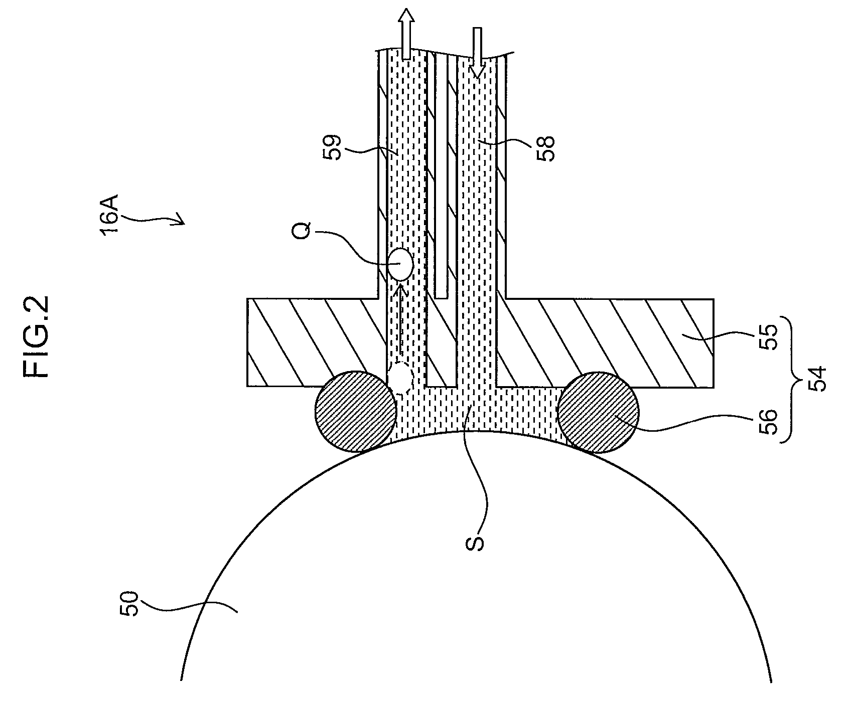
[0078]FIG. 2 is a cross-sectional diagram illustrating main components of the treatment liquid application unit 16A related to a first embodiment. As illustrated in FIG. 2, the treatment liquid application unit 16A includes a liquid holding member 54 which holds the treatment liquid in a liquid holding space S formed by causing the liquid holding member 54 to abut against the application roller 50.

[0079]This liquid holding member 54 includes a space forming base member 55 and a circular abutment member 56 which is provided on and projects from one surface of the space forming base member 55. Furthermore, a spring member 40 (see FIG. 1) is provided on the rear surface side of the liquid holding member 54 which constitutes the liquid supply device, and the liquid holding member 54 is impelled toward the circumferential surface of the application roller 50 by the impelling force of the spring member 40. The liquid holding member 54 is constituted by a space forming base member 55, and ...

second embodiment

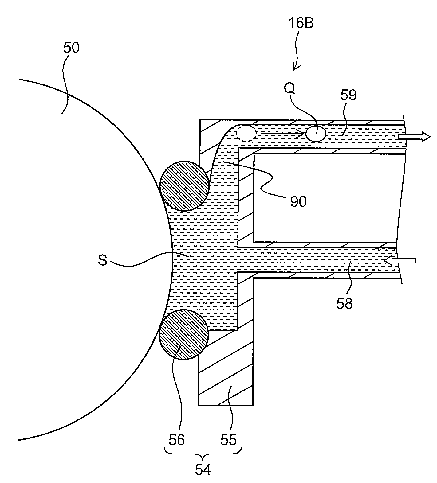
[0083]FIG. 3 is a cross-sectional diagram illustrating main components of the treatment liquid application unit 16B related to a second embodiment. The elements that are common to the devices illustrated in FIGS. 2 and 3 are assigned to the same numbers, and the description thereof is omitted here.

[0084]As is the case of the first embodiment described above, in the treatment liquid application unit 16B related to the second embodiment, the liquid recovery port 59 is arranged above the liquid supply port 58 in terms of the vertical direction as illustrated in FIG. 3.

[0085]Further, in the second embodiment, an air bubble trap part 90 is provided so as to project upward in terms of the vertical direction beyond the contact surface with the application roller 50 on the rear side of the liquid holding space S (on the opposite side of the liquid holding space S from the application roller 50), and is connected to the liquid recovery port 59.

[0086]In the second embodiment, an air bubble Q ...

third embodiment

[0087]FIG. 4 is a cross-sectional diagram illustrating main components of the treatment liquid application unit 16C related to a third embodiment. The elements that are common to the devices illustrated in FIGS. 2 and 3 are assigned to the same numbers, and the description thereof is omitted here.

[0088]As illustrated in FIG. 4, the treatment liquid application unit 16C related to the third embodiment has similar structure to the treatment liquid application unit 16A related to the first embodiment illustrated in FIG. 2, except for the liquid recovery port 59 being arranged below the liquid supply port 58 in terms of the vertical direction.

[0089]According to the third embodiment, the liquid recovery port 59 is arranged below the liquid supply port 58 in terms of the vertical direction, and therefore, in the process of the recovery operation of the treatment liquid with respect to the liquid holding space S, nearly all the treatment liquid in the liquid holding space S can be recovere...


PUM


Abstract

A liquid application apparatus includes: an application member which applies a first liquid to a recording medium; and a liquid holding member which abuts against the application member so as to form a liquid holding space in which the first liquid is held in such a manner that the first liquid held in the liquid holding space is applied to the recording medium via the application member by rotating the application member, wherein a supply port for supplying the first liquid in the liquid holding space and a recovery port for recovering the first liquid from the liquid holding space are provided in the liquid holding member, and the supply port and the recovery port are located in different positions in terms of vertical direction.

Description

BACKGROUND OF THE INVENTION[0001]1. Field of the Invention[0002]The present invention relates to a liquid application apparatus, a liquid application method and an image forming apparatus, and more particularly to liquid application technology that can be used desirably for depositing a treatment liquid on a recording medium prior to the deposition of an ink by means of an inkjet recording apparatus in order to promote aggregation of a color material of the ink, for example.[0003]2. Description of the Related Art[0004]In order to realize a high quality printing by an inkjet recording apparatus, the technology is known in which a treatment liquid, such as multivalent metal salt solution or acid aqueous solution, is deposited on a recording medium prior to depositing an ink thereon, so that the treatment liquid reacts with the ink on the recording medium so as to prevent the breeding or color mixture of the ink.[0005]Japanese Patent Application Publication No. 2005-254809 discloses a ...

Claims


Application Information

Patent Timeline
Patent Type & Authority Patents(United States)
IPC IPC(8): B41J2/01
CPCB41J2/19B41J11/0015B05C1/0813B05C1/0817
Inventor HIRATO, KATSUYUKI
Owner FUJIFILM CORP
Why Eureka
Try Eureka