

Pipe fitting inner wall flattening and grinding device
A technology for flattening and pipe fittings, which is applied in the field of flattening and grinding devices for the inner wall of pipe fittings, which can solve the problems of inability to adapt to the processing needs of pipe fittings of different sizes, poor working stability, and low processing efficiency, and achieve the effect of improving application stability
- Summary
- Abstract
- Description
- Claims
- Application Information
AI Technical Summary
Problems solved by technology
Method used
Image

Examples
Embodiment 1
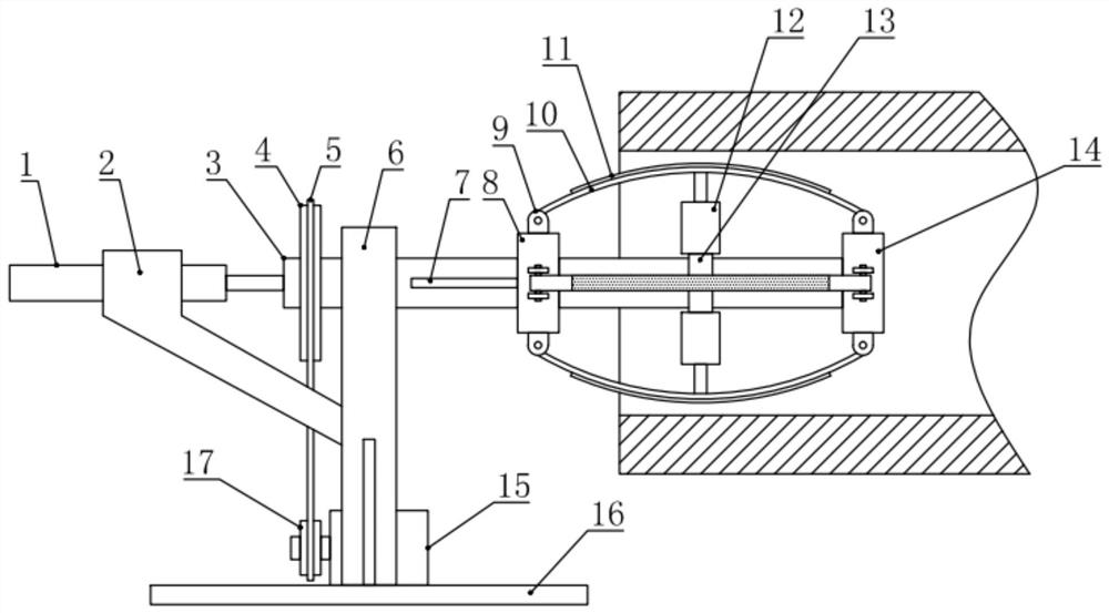
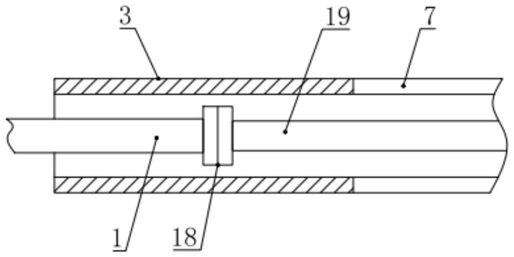
[0019] see figure 1 , in an embodiment of the present invention, a device for flattening and grinding the inner wall of a pipe fitting includes a frame 6 and a floor seat 16, the frame 6 is fixed on the floor seat 16, and the frame 6 is rotatably mounted with a transverse pipe 3 , the horizontal rotation tube 3 is driven and rotated by the driving assembly installed on the base plate base 16, the right end of the horizontal rotation tube 3 is fixed with a fixed sleeve 14, and the horizontal rotation tube 3 between the frame 6 and the fixed sleeve 14 is also fitted with sliding A movable sleeve 8 is provided, and a plurality of elastic plates 10 are installed circumferentially between the movable sleeve 8 and the fixed sleeve 14. A frosted layer 11 is provided on the outside of the elastic plate 10, and the elastic plate 10 is close to the side of the horizontal rotation tube 3. A damping assembly 12 is also installed and fixed in the middle of one side, and the other end of th...
Embodiment 2
[0022] see Figure 1-5 , the difference between this embodiment and embodiment 1 is:
[0023] In this example, if figure 1 As shown, the drive assembly includes a driven pulley 4, a V-belt 5, a servo motor 15 and a driving pulley 17, the servo motor 15 is fixed on the floor seat 16, and the output shaft of the servo motor 15 is fixed with The driving pulley 17, the driven pulley 4 is installed and fixed on the horizontal rotation tube 3, and the driven pulley 4 is connected with the driving pulley 17 through the V-belt 5, and the servo motor 15 can drive the horizontal rotation Tube 3 rotates.
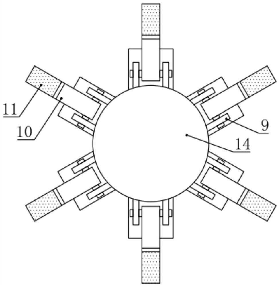
[0024] In this example, if figure 2 As shown, there are six elastic plates 10 evenly distributed in the circumferential direction, and the two ends of the elastic plates 10 are hingedly connected with the outer sidewalls of the movable sleeve 8 and the fixed sleeve 14 respectively through hinge supports 9, and the elastic plates 10 are made of metal materials. , the elastic plate ...
PUM
 Abstract
Description
Claims
Application Information