External fixation system

a fixation system and external technology, applied in the field of external fixation system, can solve the problems of limited componentry, very rapid application, long and daunting process,

Active Publication Date: 2012-12-18
STRYKER EURO OPERATIONS HLDG LLC
View PDF59 Cites 98 Cited by
  • Summary
  • Abstract
  • Description
  • Claims
  • Application Information

AI Technical Summary

Problems solved by technology

These frames are characterized by limited componentry and very rapid application.
However, mastery of the techniques and the products themselves is a long and daunting process that it is not attractive to many users.
The Ilizarov system can provide an external fixation device that could provide gradual correction along and about six axes; however, such a device would require many parts and would be relatively complicated to build and use in a clinical situation.

Method used


Image

  • External fixation system
  • External fixation system
  • External fixation system

Examples


example

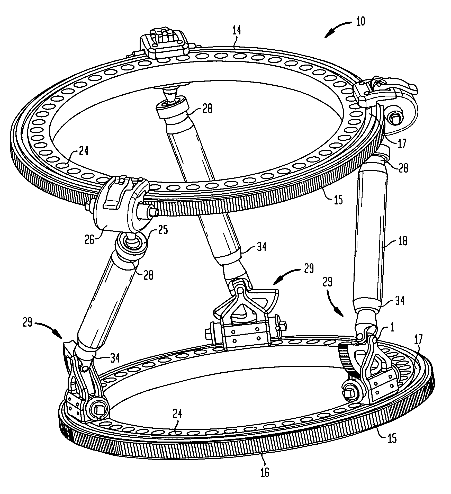
[0098]Thus, to align a first bone element with respect to a second bone element, one utilizes the above mathematical model to design software. The software will first consider the initial position of the rings with respect to the bone elements. The final position of the frame with the aligned bones will be determined by the software, taking into account the size and position of the rings and struts. The software will calculate the shortest trajectory from the initial to final position of the moving ring, generating the intermediate positions of the moving elements on the ring, and the angular rotations of the struts at the fixed ends, using a form of ring kinematics to get the necessary values. The ring kinematics will be derived by applying the mathematical formula above to determine the iterations required to get from the initial position to the final position. These iterations will be generated with a constraint on the maximum possible correction per day as defined by the surgeon...


PUM


Abstract

An external fixation system comprising: first and second planar at least part-circular ring elements, the first ring element having a circumferential track extending along the part-circular circumference thereof; a plurality of struts each having a first and second end, the first end of each strut coupled to the first ring by a first connector and the second end of each strut coupled to a second ring by a second connector, the first connector including a spherical joint; the second connector non-rotatably coupled to the second ring, the strut second end being coupled to the second connector by a U-joint; shuttles mounted on the track of the first ring for movement there along with one shuttle coupled to each strut; and means for controlling the angular position of each strut second end and means for controlling the position of each shuttle along the circumferential track on the first ring.

Description

CROSS-REFERENCE TO RELATED APPLICATION[0001]This application claims the benefit of the filing date of U.S. Provisional Patent Application No. 61 / 209,677 filed Mar. 10, 2009, the entire disclosure of which is hereby incorporated herein by reference.BACKGROUND OF THE INVENTION[0002]The external fixation market can be divided into two major segments: acute trauma and reconstructive. The customers, products, and needs of each segment are distinctly different. The trauma segment is dominated by modular fixators. These frames are characterized by limited componentry and very rapid application. Consequently, they are known for being fairly simple products. Most of these frames are used for temporizing fixation and quite often are only on the patient for hours or days.[0003]The reconstructive segment leans heavily toward ring fixation, but unilateral frames also enjoy an appreciable market share. Ring fixators such as the well known Ilizarov frame are by far the most stable and capable of e...

Claims


Application Information

Patent Timeline
Patent Type & Authority Patents(United States)
IPC IPC(8): A61F5/04
CPCA61B17/62A61B2019/461A61B17/66A61B2090/061
Inventor EDELHAUSER, ADAM JOHNTOMASHESKI, RICHARD J.
Owner STRYKER EURO OPERATIONS HLDG LLC
Why Eureka
Try Eureka