Magnetic suspension spherical active joint

A technology of active joints and magnetic levitation, applied in the directions of manipulators, manufacturing tools, joints, etc., can solve the problems of decreased precision, slow response and low efficiency of the control system, and achieve the effect of good dynamic performance, fast response speed and simple structure

Inactive Publication Date: 2009-09-23
YANGZHOU UNIV
View PDF0 Cites 24 Cited by
  • Summary
  • Abstract
  • Description
  • Claims
  • Application Information

AI Technical Summary

Problems solved by technology

This will lead to complex structure, large volume, serious wear of joint friction surfaces, low efficiency, very difficult manufacturing and installation, small range of motion space, slow response, and poor dynamic performance.
Moreover, the accumulation of errors in the mechanical transmission system leads to a decrease in the accuracy of the entire control system, and even affects the stability of the system.

Method used


Image

  • Magnetic suspension spherical active joint
  • Magnetic suspension spherical active joint
  • Magnetic suspension spherical active joint

Examples


Embodiment Construction

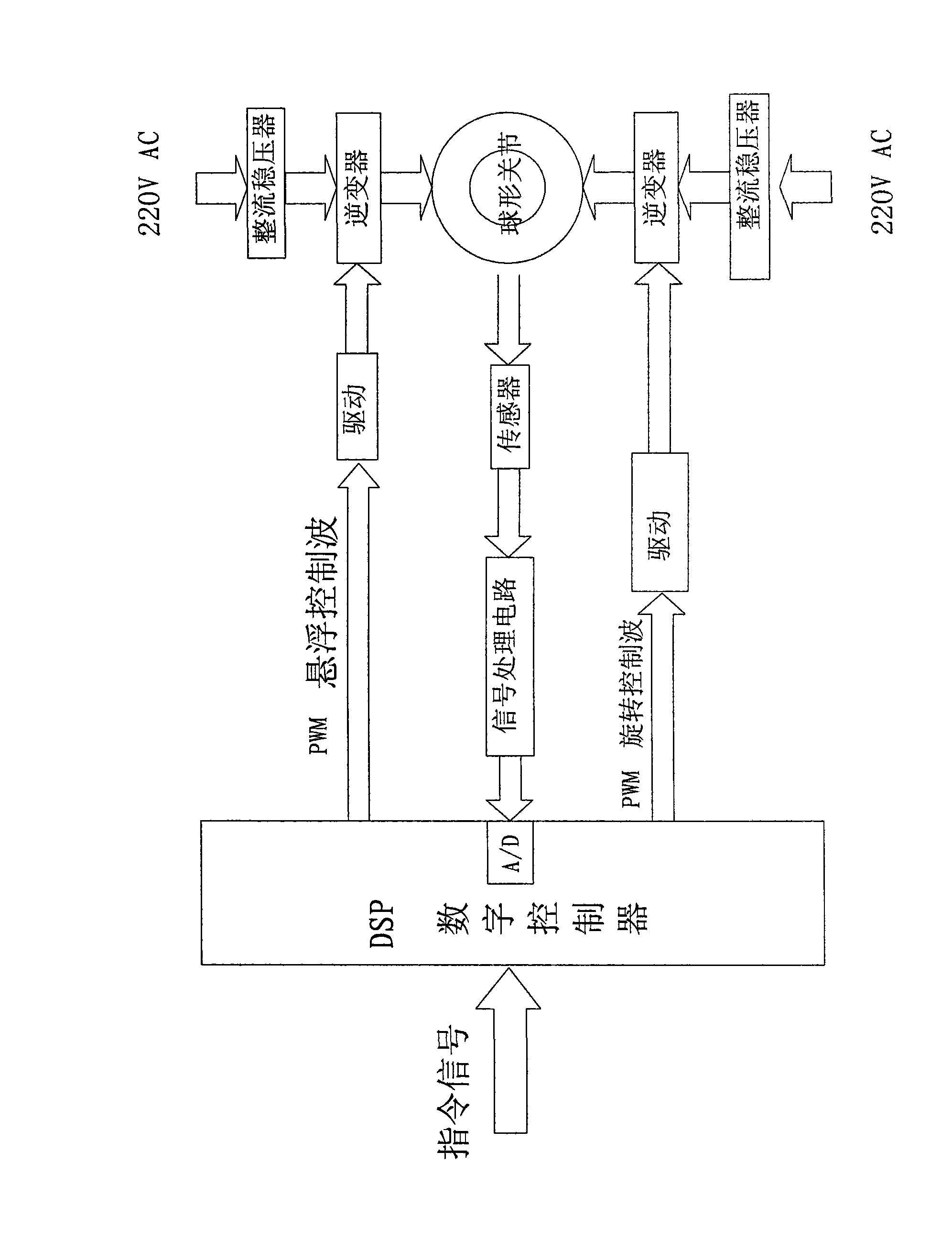
[0017] Such as figure 1 As shown, the magnetic levitation spherical active joint is composed of a spherical joint body, a power amplifier, an inverter, a rectifier regulator, a driver, a sensor, a signal processing circuit, and a DSP digital controller.

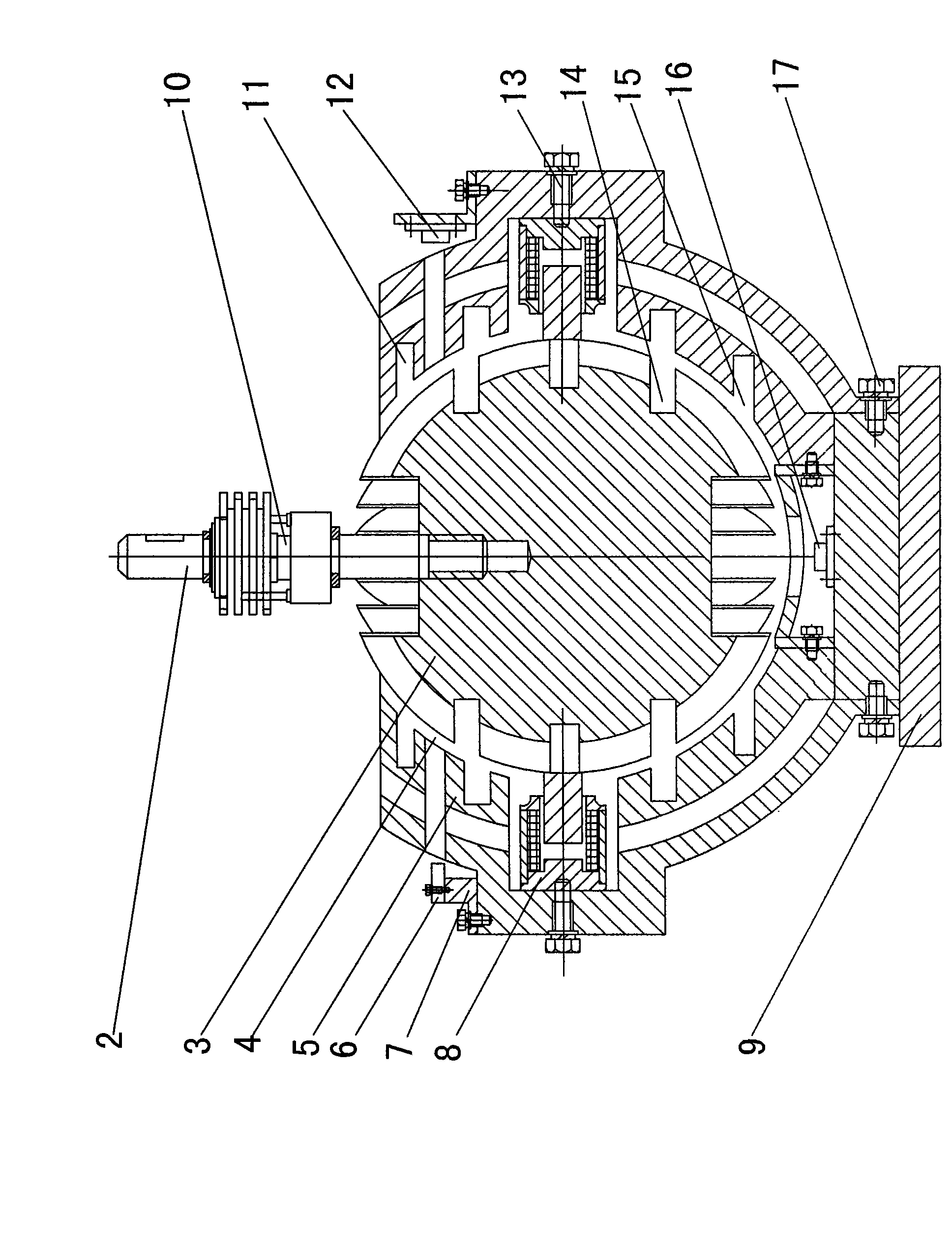
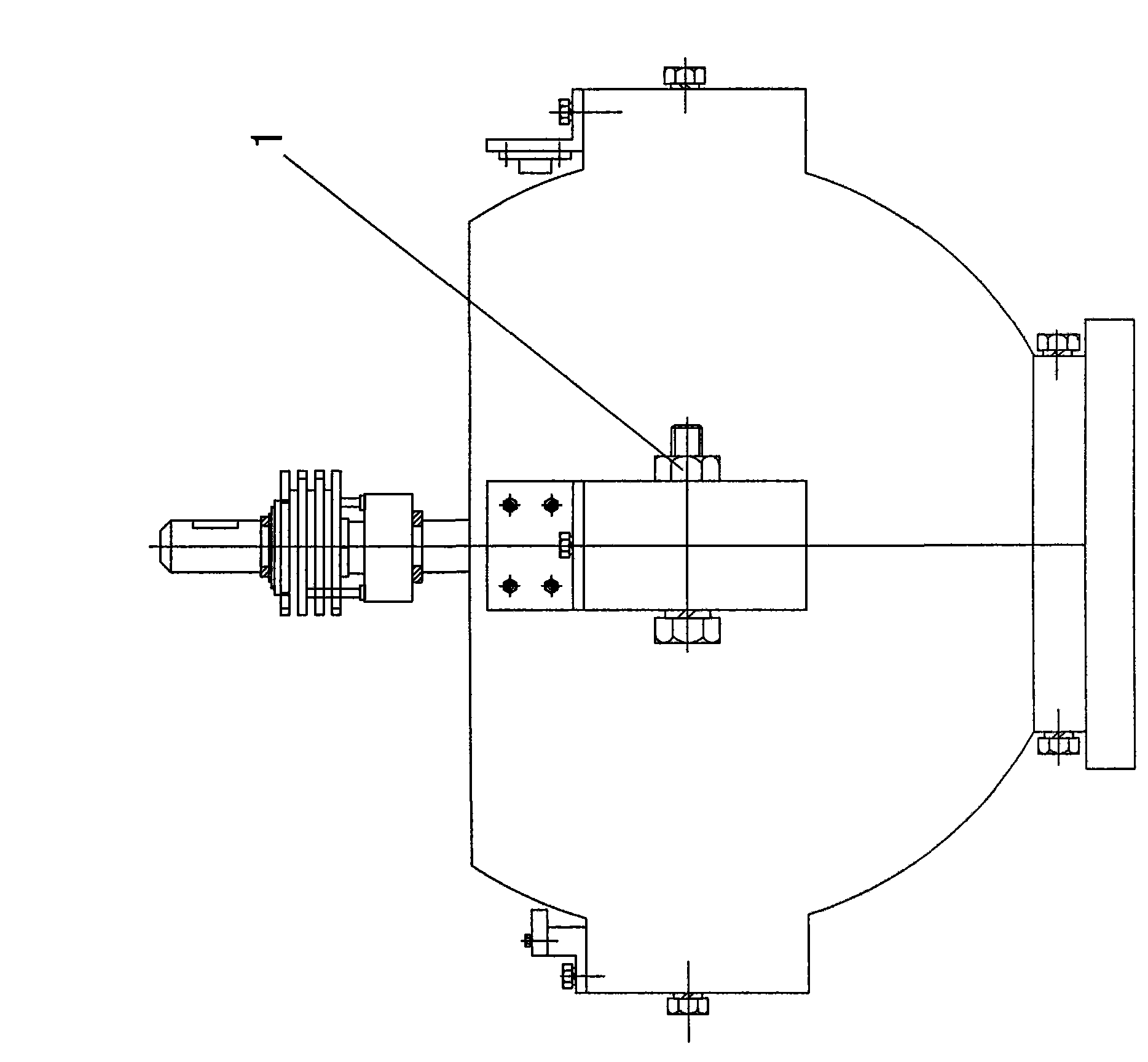
[0018] Such as figure 2 , image 3 As shown, the spherical joint body structure is composed of a base 9 supporting the joint, a joint rotor 3, a joint stator 5, a rotating arm 2, and the like. The base 9 and the magnetically suspended (bearingless) spherical joint stator 5 are fixed as a whole by connecting screws 17. The inner shape of the joint stator 5 is an open spherical inner surface, and a groove 11 is formed on the spherical inner surface, and the groove connects the entire spherical inner surface. It is divided into tiny unit faces with the same geometric shape to form an inner spherical salient pole stator. And along the grooves parallel to each three-dimensional coordinate plane with the center of the sphere as...


PUM


Abstract

A magnetic suspension spherical active joint belongs to the technical field of electromechanical integration. The magnetic suspension spherical active joint comprises a base, a joint stator, a joint rotor, a rotor arm and a detection control system, wherein the base and the joint stator are fixed into a whole; the inside of the joint stator is a spherical inner surface with an opening in shape; the joint rotor is arranged inside the joint stator; the joint rotor and the rotor arm are fixed into a whole; the rotor arm extends to the outer end through the opening of the joint stator; certain air gap exists between the spherical inner surface of the joint stator and the spherical outer surface of the joint rotor when both are concentric; and the joint stator is provided with at least two clamping mechanisms and a plurality of sensors for detecting the position and the moving speed of the joint rotor. Magnetic suspension technology and motor technology are integrally applied to realize suspension support of the spherical joint and drive the joint rotor to rotate. The invention has simple and compact structure, favorable dynamic performance and rapid response speed, and realizes no friction and no abrasion between the spherical joint rotor and the joint stator.

Description

technical field [0001] The invention relates to a joint system with supporting and driving functions widely used in engineering, especially the joints of robots and manipulators, and belongs to the technical field of mechatronics. Background technique [0002] Spherical joints are used in robots and manipulators, as well as multi-coordinate machining centers, Hangda aircraft, electric gyroscopes, omni-directional tracking antennas, turret turntables, medical equipment, camera consoles, panoramic photography consoles, mixers, and universal wheels for moving mechanisms , spherical valves, spherical pumps and other equipment with multiple degrees of freedom of motion have broad application prospects. The joint system includes drives, transmissions and controllers, which are the basic components of the robot and an important link in the entire robot servo system. Its structure, weight, and size have a direct impact on the performance of the robot. The driving methods of joints ...

Claims


Application Information

Patent Timeline
Patent Type & Authority Applications(China)
IPC IPC(8): B25J17/00B25J13/00
Inventor 曾励张丹刘静姜明明王张合
Owner YANGZHOU UNIV
Why Eureka
Try Eureka