
Network system

a network system and network technology, applied in the field of network systems, can solve the problems of frequent replacement of batteries of remote controllers, frequent loss of remote controllers, etc., and achieve the effect of convenient control of devices using

Active Publication Date: 2012-12-18
LINUXIT
View PDF2 Cites 0 Cited by
  • Summary
  • Abstract
  • Description
  • Claims
  • Application Information

AI Technical Summary

Benefits of technology

"The present invention provides a network system for controlling devices which operate in response to infrared signals, even at long distances or in the presence of obstacles. The system includes modules which output infrared signals for controlling devices and analyze path information of command data. The modules have identification numbers for easy identification and authentication, and can communicate with a home server to control the devices. The technical effect of the invention is to provide a convenient and efficient way to control devices which operate in response to infrared signals."

Problems solved by technology

However, such remote controllers have many disadvantages.
For example, the remote controllers are frequently lost, and their batteries are required to be frequently replaced with new ones.
However, products, which have been developed before the home network systems are commonly used, are not controlled by the home network systems.
Also, although devices, which have been developed before home network systems are commonly used, are controlled using an infrared signal controlling apparatus, a problem may occur due to the linearity of an infrared signal or an obstacle may be positioned in the middle of the infrared signal.
If the devices are too distant from the infrared signal controlling apparatus for the infrared signal to reach the devices, the devices may not be conveniently controlled by the infrared signal.

Method used


Image

  • Network system
  • Network system
  • Network system

Examples


Embodiment Construction

Technical Problem

[0006]The present invention provides a network system for conveniently controlling devices which operate in response to an infrared signal in spite of their long distance positions or obstacles in front of them.

Technical Solution

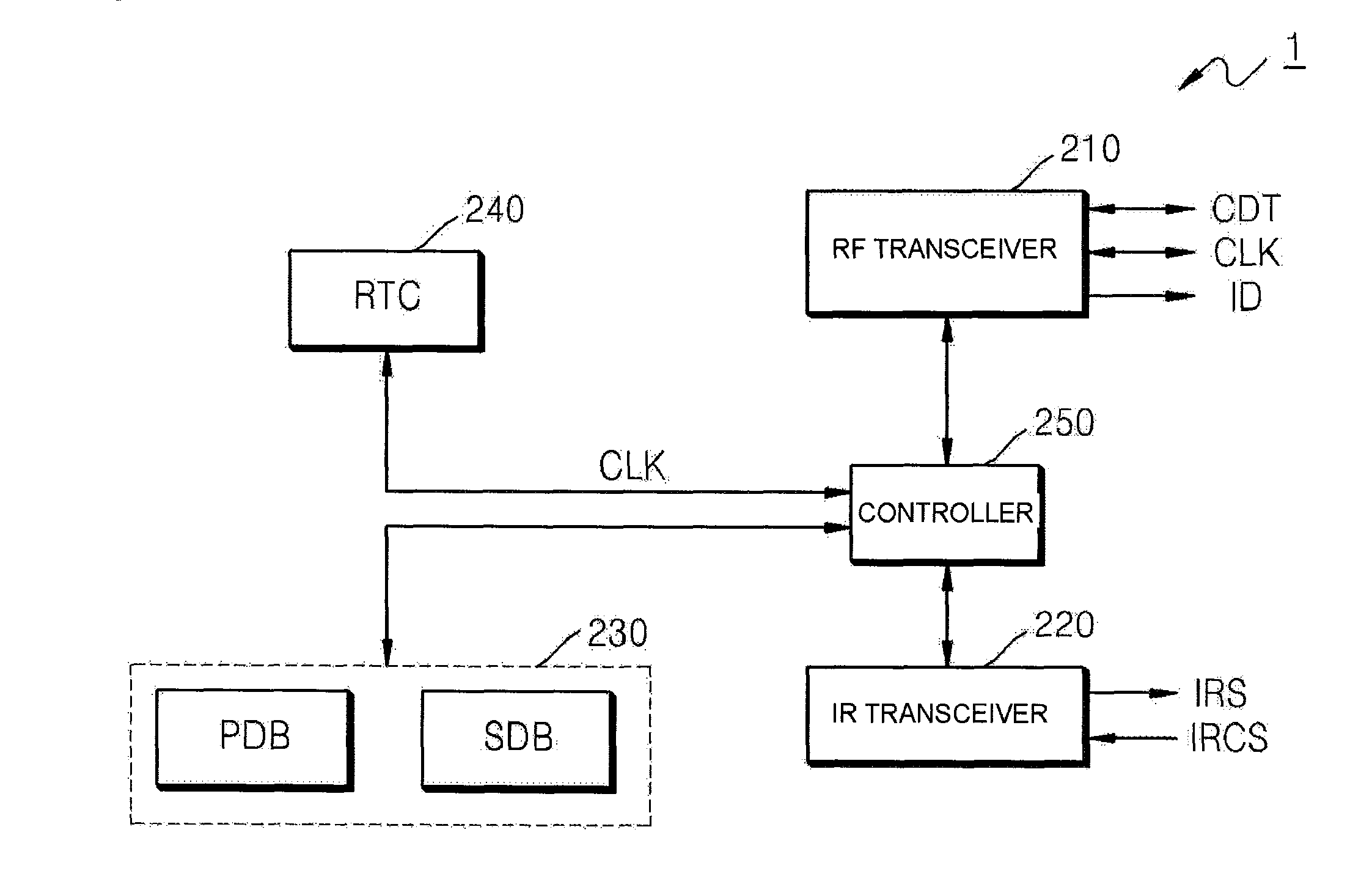
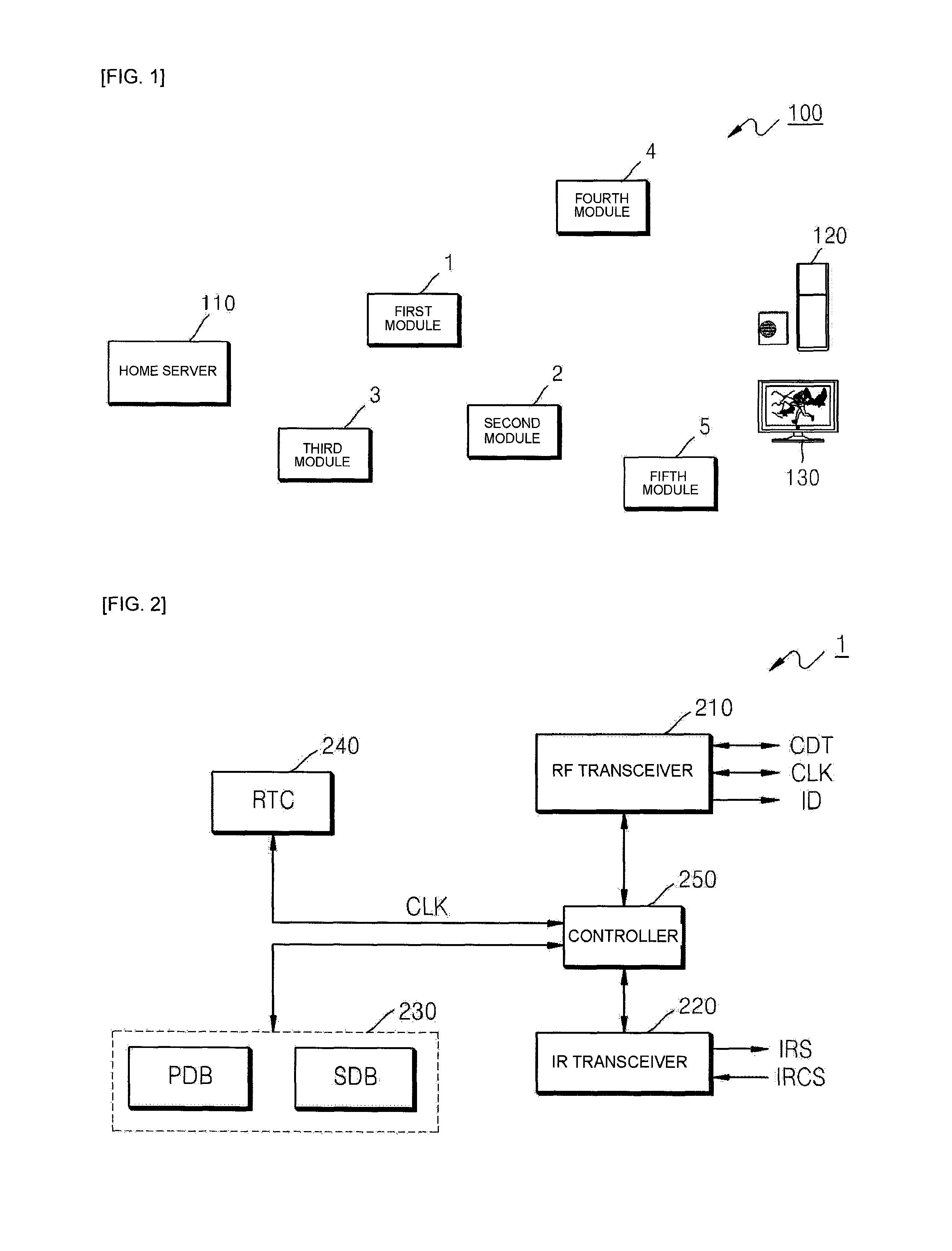
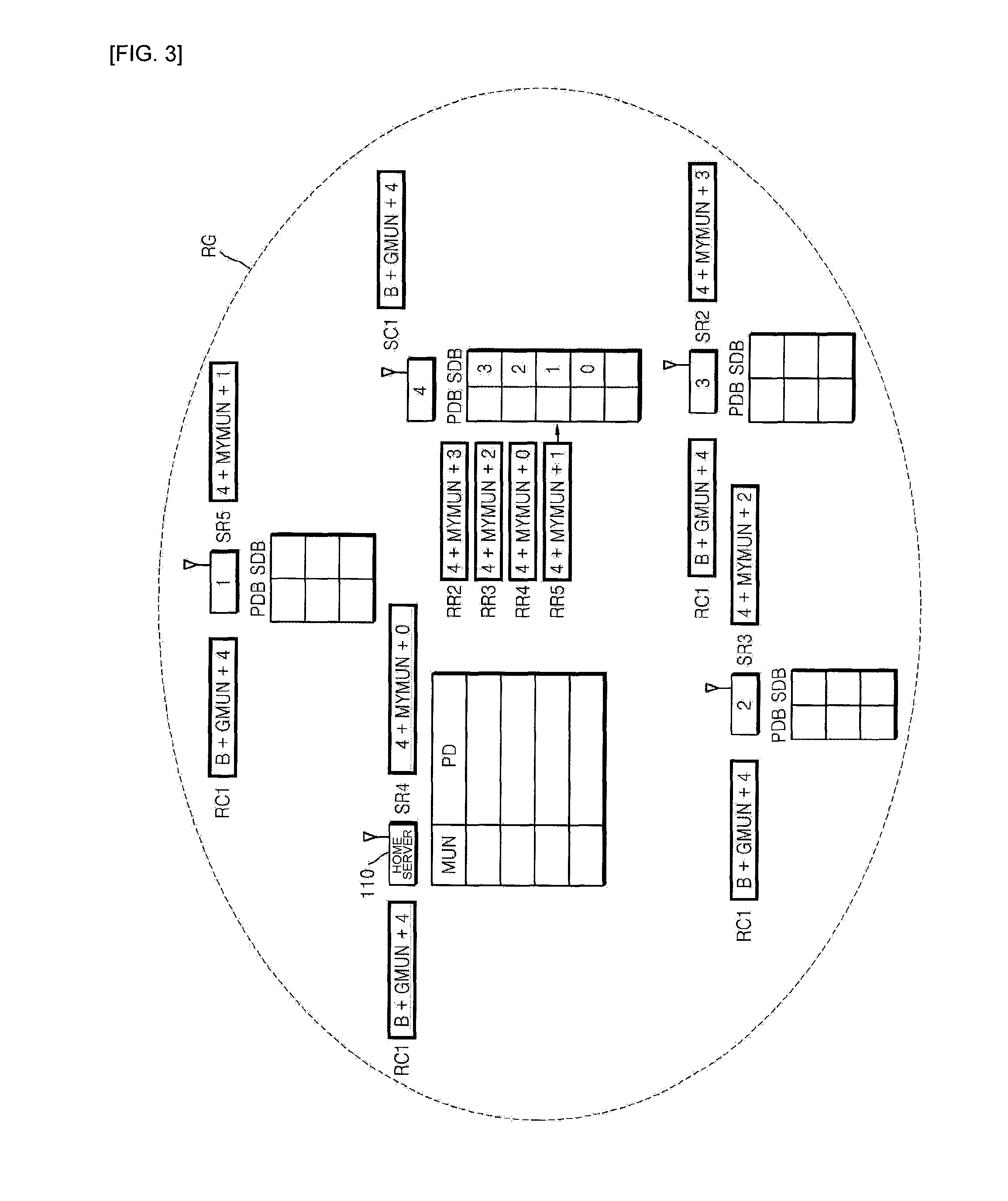
[0007]According to an aspect of the present invention, there is provided a network system for controlling devices which operate in response to an infrared signal, including: modules which output an infrared signals for controlling the devices in response to command data or analyze path information of the command data, forward the command data to next one of the modules, and receive infrared control signals generated by the devices; and a home server which includes identification (ID) numbers of the modules and the path information of the command data for allowing the command data to reach each of the modules and outputs the command data or receives the infrared control signals.

[0008]Each of the modules may include: a radio frequency (RF) tra...


PUM


Abstract

Provided is a network system for controlling devices which operate in response to an infrared signal. The network system includes modules and a home server. The modules output the infrared signal for controlling the devices in response to command data or analyze path information of the command data, forward the command data to next one of the modules, and receive infrared control signals generated by the devices. The home server includes ID numbers of the modules and the path information of the command data for allowing the command data to reach each of the modules and outputs the command data or receives the infrared control signals. Therefore, the network conveniently control the devices using the infrared control signal even when the modules are too distant from the home server for the infrared signal to reach the devices at a time or obstacles are placed in front of the modules. Also, the network system performs authentication processes among the modules using time information to prevent the modules from malfunctioning by another infrared signal or command data.

Description

[0001]This is a National Phase Application filed under 35 U.S.C. 371 as a national stage of PCT / KR2008 / 004260, filed on Jul. 22, 2008, an application claiming the benefit of Korean Patent Application 10-2007-0076918, filed on Jul. 31, 2007, the entire content of each of which is hereby incorporated by reference in its entirety.TECHNICAL FIELD[0002]The present invention relates to a network system, and more particularly, to a network system for controlling devices which operate in response to an infrared signal.BACKGROUND ART[0003]In general, television (TV) sets, beam projectors, air conditioners, air cleaners, etc. used in homes are controlled by infrared remote controllers. Since such devices used in a home individually have their own remote controllers, several remote controllers are required to control the devices. However, such remote controllers have many disadvantages. For example, the remote controllers are frequently lost, and their batteries are required to be frequently r...

Claims


Application Information

Patent Timeline
Patent Type & Authority Patents(United States)
IPC IPC(8): H04B10/10
CPCH03J9/06H04L12/282H04L2012/2849H04L2012/285H04L12/12H04B7/24
Inventor KWON, GYEONG JU
Owner LINUXIT
Learn More