Double seat valve with seat cleaning

a seat valve and seat technology, applied in the field of seat valves with seat cleaning, can solve the problems of direct impact of seat cleaning flow on the surface delimiting the leakage cavity, limiting the respective quantity of cleaning agents during seat cleaning, and more or less elaborate, so as to avoid the creation of turbulence

Active Publication Date: 2012-12-25
GEA TUCHENHAGEN GMBH
View PDF9 Cites 9 Cited by
  • Summary
  • Abstract
  • Description
  • Claims
  • Application Information

AI Technical Summary

Benefits of technology

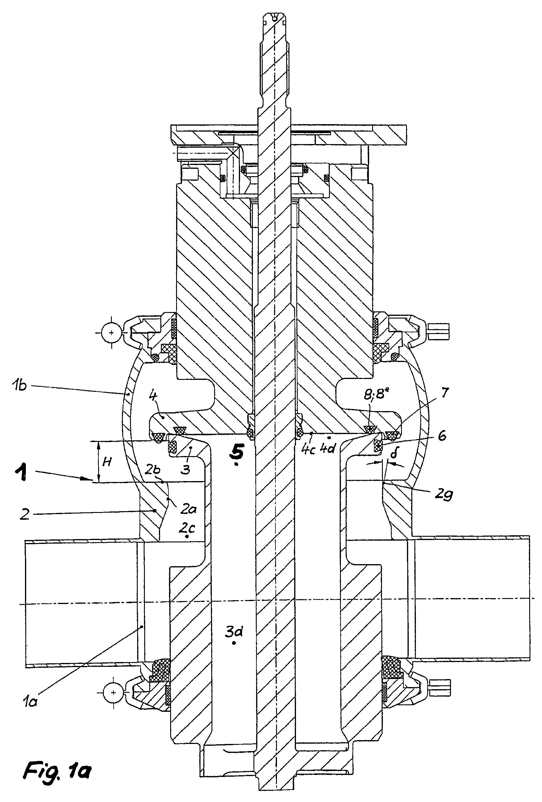
[0014]With the flow direction of the second seat cleaning flow generated by lifting the second closing element, it is essential that it breaks off in a defined manner at a first circumferential edge formed by the second seat and the first end section of the first seat, and is guided securely tangentially past the surfaces at the edge of the first closing element in the area of the leakage cavity. For this purpose, a safety offset between the first circumferential edge and the relevant areas of the first closing element is provided that prevents such an impact under all possible manufacturing conditions. A second fundamental inventive thought consists in moving the limit of the final position, the firm stop that is desirable but that is not or cannot be implemented in all cases (slider piston with radially effective seal in slide engagement or possibly seat plate with radially / axially seal in slide / pressure engagement) into its closing position at the end of the second seat, in fact immediately next to the first seat. According to the invention, this succeeds in that the second closing element in its closing position rigidly and firmly contacts the second seat in the position specified in the preceding, with a stop surface that is arranged at its periphery that is located radially inside next to its second seal. This measure removes the gap between the second closing element and the valve housing, adjacent to the leakage cavity, that was previously present, where the seal is usually made of metal. Now, in the course of cleaning the seat of the first closing element, no cleaning agent can reach the second seat seal that is defective or possibly missing entirely, through the metallically closed gap between the second closing element and the second seat.
[0020]The first opening slope proposed according to the invention facilitates the entry of the first seal into the cylindrical first seat, and thereby reduces the wear of this seal. Fluidically, however, this opening slope is rather disadvantageous, as it delays the first seat cleaning flow due to the enlargement of the flow cross-section, and thereby presents the danger of a detachment of the flow. In this context, it is proposed to represent the end section forming the first opening slope by at least one cone-shaped surface. In order to avoid that the first seat cleaning flow detaches at the contour of this cone-shaped surface, it is proposed to incline the first end section by a pitch that is implemented to be in the range between 0 and 15 degrees, preferably in the range between 5 and 15 degrees, and here in turn, preferably with 15 degrees.
[0024]In order to avoid that after leaving the deflection surface, the first seat cleaning flow streams against the center seal or the front face of the recess, creating a dynamic pressure, it is further provided that the deflection surface undercuts the front face by an axial undercut distance. Thereby, the contour of the deflection surface in the area of its outlet point can be pitched by a deflection angle with respect to the front face of the recess such that the first seat cleaning flow is tangential to the center seal, is thereby slightly diverted in the direction of the second closing element, and can then follow the wall shape of the adjacent front face of the recess in order to clean it. It has been proven advantageous if the deflection angle is implemented in the range of 5 to 20 degrees, preferably with 15 degrees.
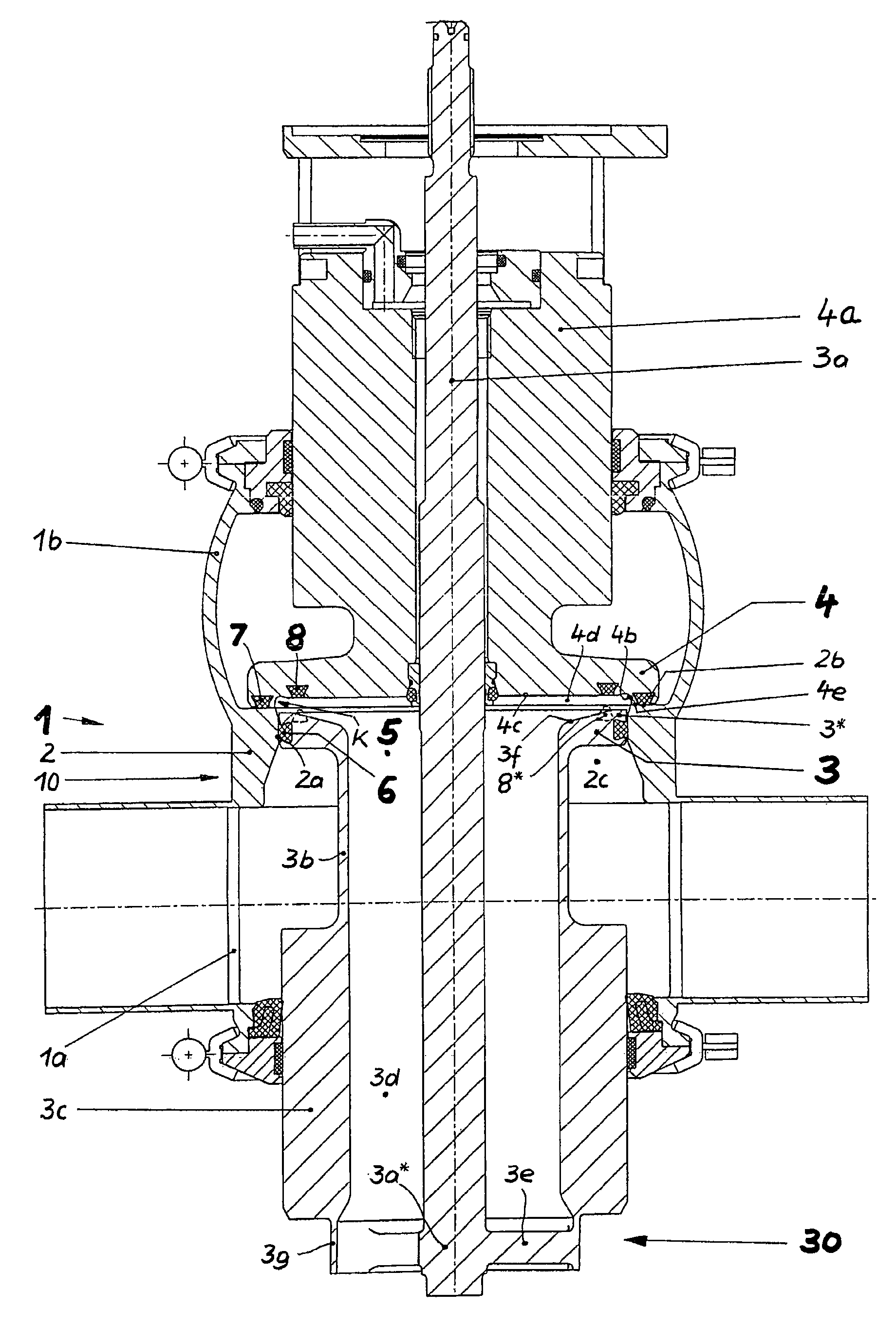
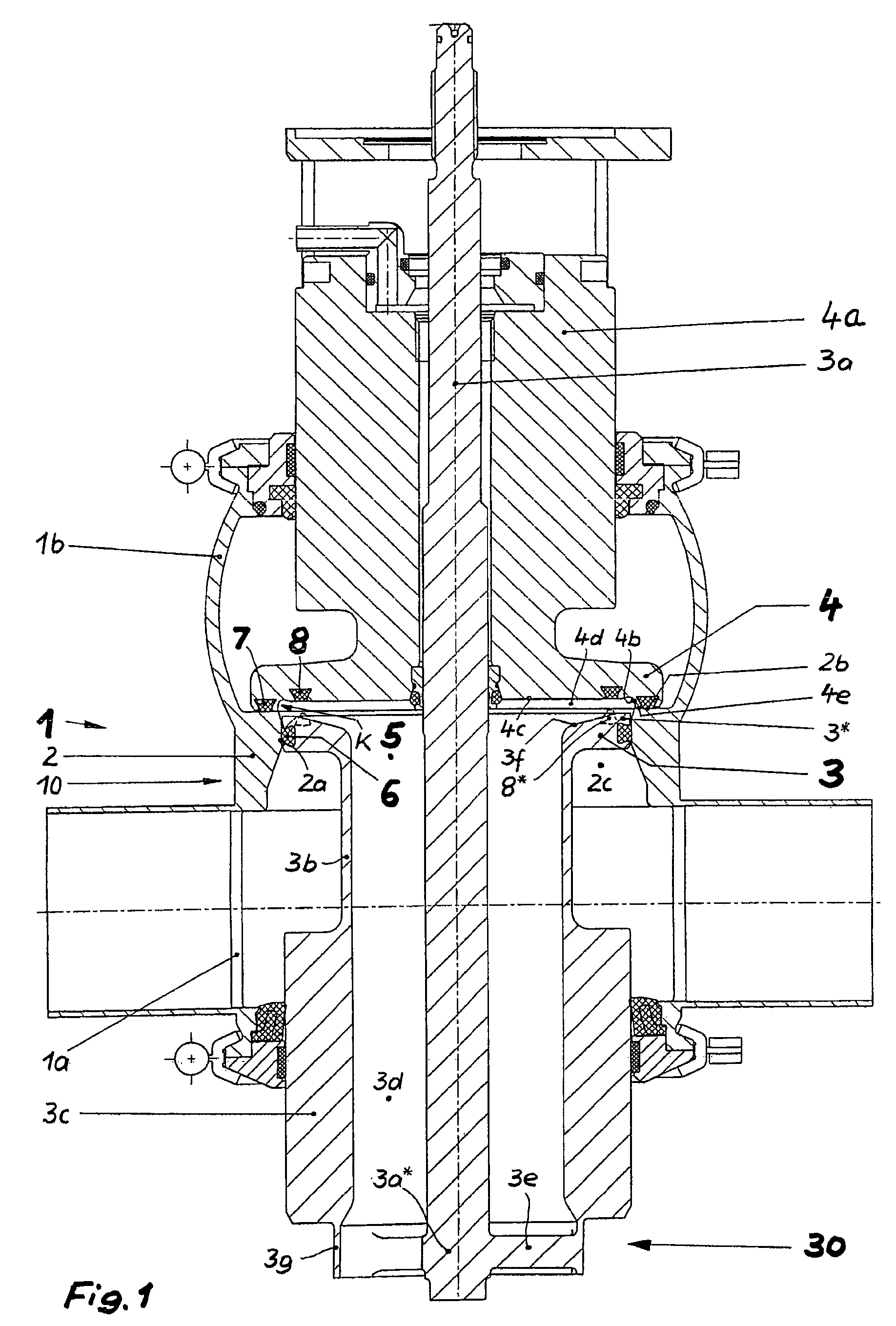
[0026]In order to avoid the creation of turbulence and dynamic pressure not only in the area of the previously described seats of the double seat valve, it is advantageous if any internal fittings or obstructions in the remaining leakage cavity are omitted if this is constructively possible. In this respect, a further proposal provides that a first displacement rod, connected to the first closing element, concentrically penetrates a second displacement rod implemented as a hollow rod, connected to the second closing element, continues flying through the drainage hole, and is rigidly connected to the first closing element at the latter's end facing away from the second closing element, via an essentially radially oriented traverse. This way, the struts and other means of connection that are otherwise customary in the area of the leakage cavity are avoided, and are relocated to a relatively distant end of the leakage cavity where they no longer can have any disturbing influences on the flow guidance.
[0027]In this context it is further proposed that three traverses are fixedly provided at a displacement rod section, said traverses are uniformly distributed over the circumference and that each is fixedly connected on its outside to a circumferential ring, and that the displacement rod section, the traverses, and the ring form an integral welded part. Here, it is further advantageous if the welded part connects on its outside via the ring to a pressure compensation piston that bounds a section of the drainage hole that is remote from the leakage cavity, and on its inside connects via the displacement rod section to the first displacement rod, and if the ring in its interior diameter is enlarged with respect to the diameter of the drainage hole, and with the intermediate arrangement of a conically expanding transition, such that the interior passage through the drainage hole is not reduced by the traverses.

Problems solved by technology

The limitation of the respective quantity of cleaning agent during the seat cleaning occurs through a more or less elaborate, and often insufficient, alignment of the opened gap between the respective seal in the associated seat.
Therefore, a direct impact of the seat cleaning flow on the surface delimiting the leakage cavity is always counterproductive.
Furthermore, at the impact point, a branching current line results whose branch facing the seat can generate turbulence there, and a dynamic pressure.

Method used


Image

  • Double seat valve with seat cleaning
  • Double seat valve with seat cleaning
  • Double seat valve with seat cleaning

Examples


Embodiment Construction

[0040]While this invention may be embodied in many different forms, there are described in detail herein a specific preferred embodiment of the invention. This description is an exemplification of the principles of the invention and is not intended to limit the invention to the particular embodiment illustrated.

[0041]A double seat valve 1 according to the invention (FIGS. 1 and 1a) consists in a first embodiment essentially of a valve housing 10 with a first and a second valve housing part 1a and 1b, two closing elements 3 and 4 that can be moved independently of each other, each with an associated displacement rod 3a and 4a, and a seat ring 2 that creates a connection between the two valve housing parts 1a and 1b through an inside connecting opening 2c.

[0042]The first closing element 3 (active closing element) that is designed as a slide piston, is received in a sealing manner in the closed position of the double seat valve 1 (FIG. 1) in a first seat 2a, formed by the connecting o...


PUM


Abstract

The invention relates to a double seat valve which is capable of cleaning the seat. The double seat valve includes a closing element (4), when in its closed position rests with a stop surface (4e), arranged on a boundary surface thereof radially adjacent on an inner side to a seal (7), on a second seating surface (2b) and directly adjacent to a first seating surface (2a, 2g) with a central recess (4d) provided in a front face of the closing element (4) facing a leakage cavity (5). The closing element (4) further includes a deflector surface (4b) opening in a front face (4c), wherein the deflector surface (4b) and the slop surface (4e) form a circumferential edge (U2) directly adjacent to a first end section (2g) of the first seating surface (2a) in the closed position of the closing element (4).

Description

CROSS-REFERENCE TO RELATED APPLICATIONS[0001]Not applicableSTATEMENT REGARDING FEDERALLY SPONSORED RESEARCH[0002]Not applicableBACKGROUND OF THE INVENTION[0003]The invention relates to a double seat valve with seat cleaning, having two serially arranged closing elements, movable relative to each other, that in the closed position of the double seat valve prevent the overflow of fluids from one valve housing part into another, and that in the closed as well as the open position define a leakage cavity, that is connected to the surroundings of the double seat valve, wherein in the closed position, the first closing element constructed as a slide piston is received in a sealing manner in the connecting opening joining the valve housing parts together, and in the course of its opening movement comes into sealing abutment with a second closing element that is assigned to a second seat and has a second seal, via a center seal acting between the closing elements, and the latter during the ...

Claims


Application Information

Patent Timeline
Patent Type & Authority Patents(United States)
IPC IPC(8): F16K1/44
CPCF16K1/446Y10T137/4245Y10T137/4259Y10T137/5762Y10T137/88038
Inventor BURMESTER, JENSSUEDEL, MATTHIAS
Owner GEA TUCHENHAGEN GMBH
Why Eureka
Try Eureka