
Traversing jet actuator

a jet actuator and transverse technology, applied in the field of fixed-wing aircraft, can solve the problems of increasing the coefficient of lift for the wing and ultimately adding drag, and a challenge to the amount of lift generated by the aircraft's wings

Active Publication Date: 2012-12-25
THE BOEING CO
View PDF23 Cites 15 Cited by
  • Summary
  • Abstract
  • Description
  • Claims
  • Application Information

AI Technical Summary

Benefits of technology

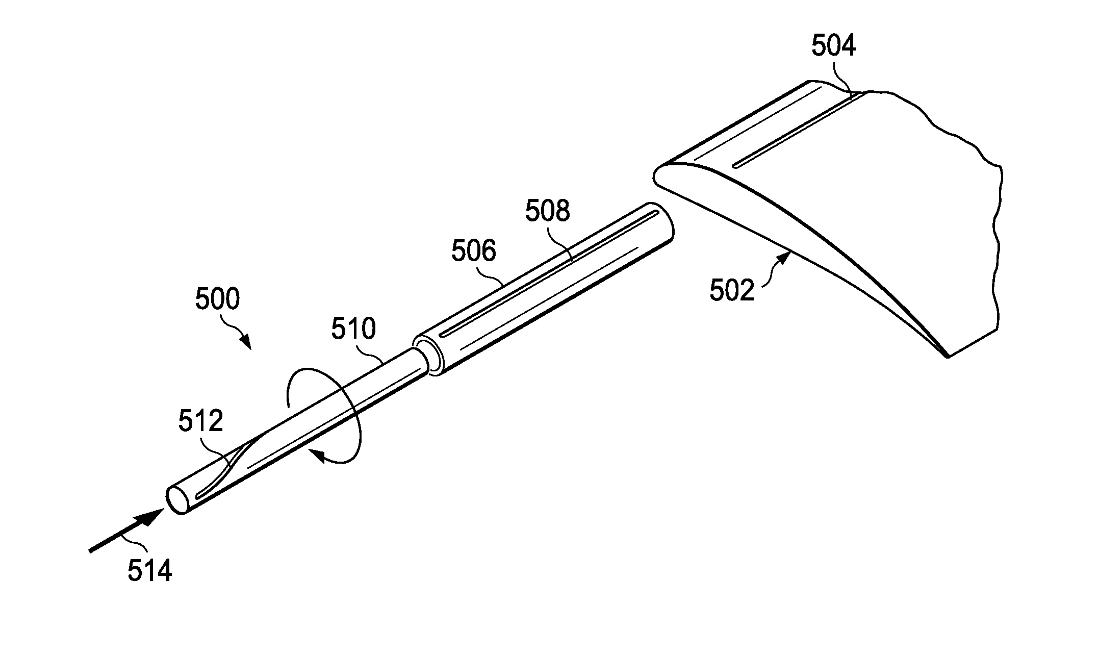
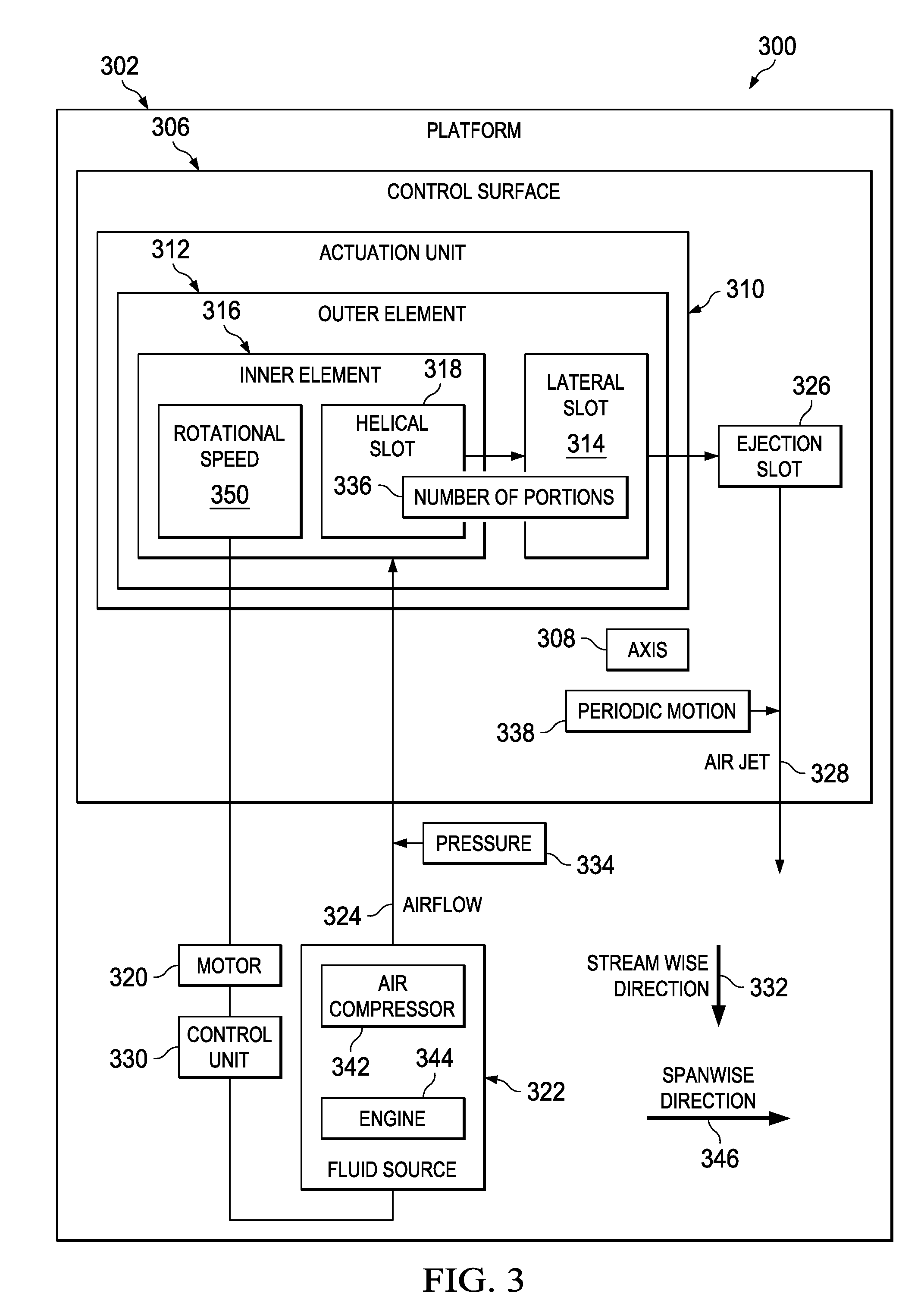
The patent describes an apparatus and method for moving air across a control surface of an aircraft. The apparatus includes a platform, actuation unit, fluid source, and control unit for moving an air jet across the control surface. The control surface has a slot that sends a stream of air in a periodic motion along its spanwise direction. The method also involves positioning an inner element inside an outer element, with the inner element rotated inside the outer element by a motor. The outer element has a lateral slot, and the inner element has a helical slot that wraps around its outer surface. The technical effects of this invention include improved airflow control and reduced airflow resistance, which can lead to improved aircraft performance.

Problems solved by technology

The amount of lift generated by the aircraft's wings can be a challenge during take-off and landing periods when airspeed levels are lower.
Flaps increase the camber of the wing airfoil, which increases the coefficient of lift for the wing and ultimately the amount of lift generated.
However, flaps also may add drag and increase the airframe noise generated by the aircraft.
However, there are limits on how much additional lift can be generated.
This can make landing difficult due to restrictions.
Also, it may pose a risk of the tail of the aircraft contacting the runway.
This risk can be reduced by using longer landing gear, but will result in greater airplane weight.
This lack of turning tends to create a separation pocket or a lack of attachment of the flow around the upper surface of the wing or flap.
However, current methods of airflow control require substantial amounts of ejected airflow to achieve meaningful design targets.
The aircraft engines can be used to supply air for actuation by “bleeding” compressed air from inside the engine, but design targets require substantial amount of bleed air.
The requirement of engine bleed impacts the size and efficiency of the aircraft engines.
The larger the bleed requirement, the larger and heavier the engine needed.
Larger and heavier engines lead to an increase in aircraft gross weight and engine cost.
In addition, bleed requirements reduce the efficiency of the engines.
However, the addition of separate air compressors also leads to additional weight.

Method used


Image

  • Traversing jet actuator
  • Traversing jet actuator
  • Traversing jet actuator

Examples


Embodiment Construction

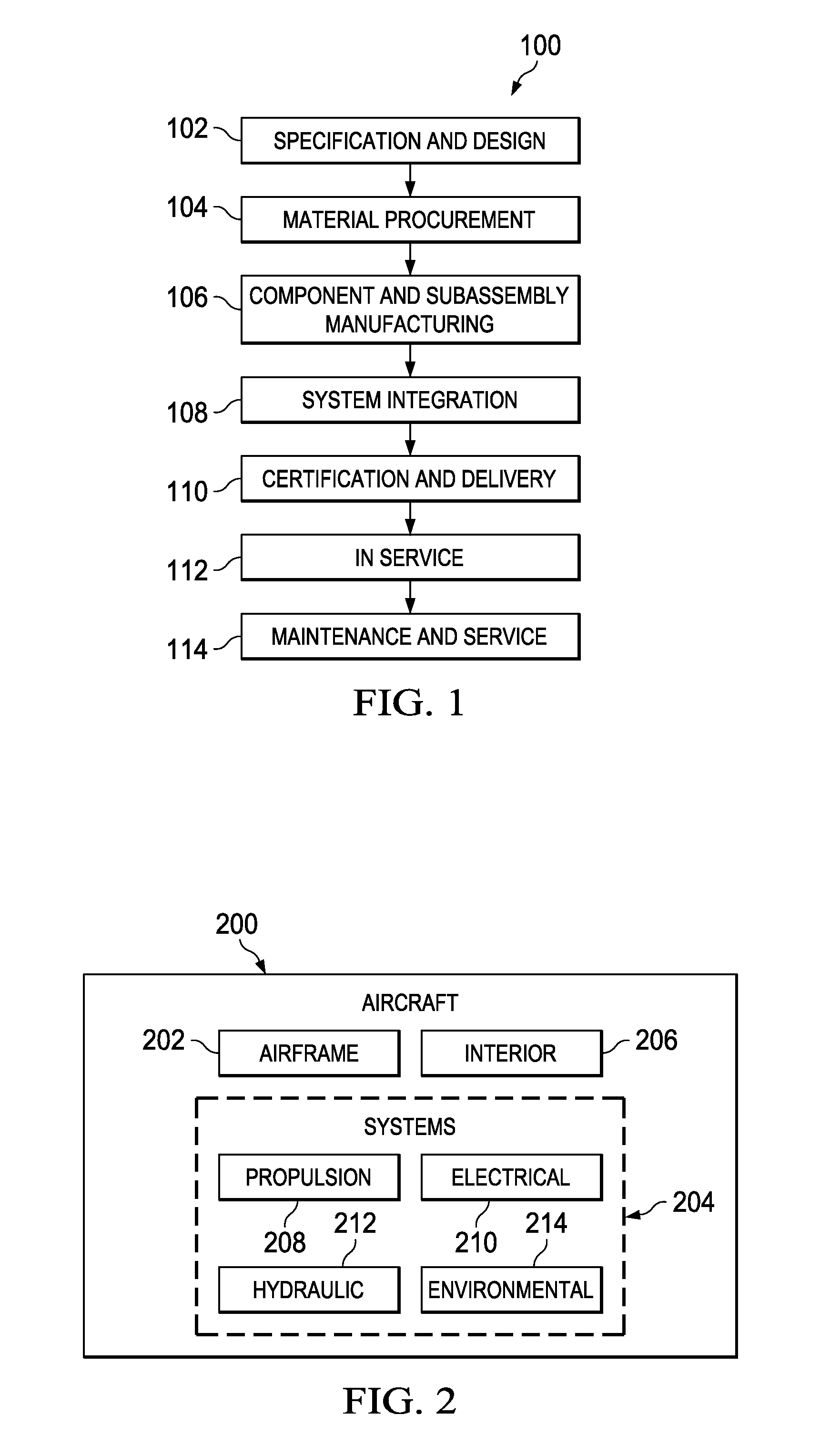
[0035]Referring more particularly to the drawings, embodiments of the disclosure may be described in the context of aircraft manufacturing and service method 100 as shown in FIG. 1 and aircraft 200 as shown in FIG. 2. Turning first to FIG. 1, an illustration of an aircraft manufacturing and service method is depicted in accordance with an advantageous embodiment. During pre-production, aircraft manufacturing and service method 100 may include specification and design 102 of aircraft 200 in FIG. 2 and material procurement 104.

[0036]During production, component and subassembly manufacturing 106 and system integration 108 of aircraft 200 in FIG. 2 takes place. Thereafter, aircraft 200 in FIG. 2 may go through certification and delivery 110 in order to be placed in service 112. While in service by a customer, aircraft 200 in FIG. 2 is scheduled for routine maintenance and service 114, which may include modification, reconfiguration, refurbishment, and other maintenance or service.

[0037]...


PUM


Abstract

An apparatus comprises a platform configured to move in a streamwise direction, an actuation unit associated with a control surface of the platform, a fluid source configured to supply an airflow to the actuation unit, and a control unit for moving an air jet across the control surface. The actuation unit is configured to form a traversing air jet pointing in the streamwise direction.

Description

BACKGROUND INFORMATION[0001]1. Field[0002]The present disclosure relates generally to aircraft and, in particular, to a method and apparatus for a fixed-wing aircraft. Still more particularly, the present disclosure relates to a method and apparatus for a fixed-wing aircraft with increased lift.[0003]2. Background[0004]A fixed-wing aircraft is a heavier-than-air vehicle capable of flying in the air. A fixed-wing aircraft is capable of flying due to lift, which is generally generated by the wings of the aircraft. The amount of lift generated by the wings of a fixed-wing aircraft is proportional to the airspeed of the aircraft. At lower airspeeds the wings of an aircraft generate less lift. If the airspeed of the fixed-wing aircraft drops below a stall speed, less lift is created. The amount of lift generated by the aircraft's wings can be a challenge during take-off and landing periods when airspeed levels are lower.[0005]Flaps are generally used on most fixed-wing aircraft to create...

Claims


Application Information

Patent Timeline
Patent Type & Authority Patents(United States)
IPC IPC(8): B64C3/00B64C21/04
CPCB64C9/18B64C9/38B64C21/04Y02T50/166Y02T50/32Y02T50/30Y02T50/10B64C9/16B64C21/08
Inventor SHMILOVICH, ARVINYADLIN, YORAMCLARK, ROGER W.
Owner THE BOEING CO
Learn More