
Electric oscillating drive

a technology of oscillating drive and electric motor, which is applied in the direction of electrical apparatus, mechanical vibration separation, dynamo-electric machines, etc., can solve the problems of affecting the working member, the diaphragm of the pump, and the oscillating characteristic deviating from parallelism, and achieves weak flexural elastic

Inactive Publication Date: 2012-12-25
RICHTER SIEGFRIED
View PDF9 Cites 0 Cited by
  • Summary
  • Abstract
  • Description
  • Claims
  • Application Information

AI Technical Summary

Benefits of technology

"The present invention provides an electric oscillating drive with a compact design, simple manufacturing process, and low cost. The drive has flexible arms and a driving lever that work together to generate pendular oscillations. The system does not require additional spring elements for restoring forces, and can be easily synchronized to drive two working members. The double oscillating system can be controlled and synchronized, and can be used with a fluid pump or air pump. The invention offers a solution for achieving efficient and reliable oscillating motion with a simple and cost-effective design."

Problems solved by technology

However, high bending elasticity may lead to an oscillating characteristic deviating from parallelism.
The resonant mass fastened to the end section of the balance arm, which said end section is connected to the connection arc, and the coupling member connected thereto [said resonant mass—Tr.Ed.] do not perform any pure parallel oscillation in relation to the plane in which the valance arm extends, but an arc-shaped motion, which may have a harmful effect on the working member, i.e., on the pump diaphragm.
However, a three-legged resonant spring is disadvantageous because it requires more space than an only two-legged spring and because it can get out of step more easily, i.e., it is more prone to trouble.
In addition, it is more difficult to tune a three-legged spring to the adequate natural frequency than a two-legged one.
The resonant spring and balance spring consist of leaf springs each with high spring elasticity in this prior-art drive device, which experience has shown to be able to lead rather to resonance deviations and hence to operating troubles when a resisting force develops.

Method used


Image

  • Electric oscillating drive
  • Electric oscillating drive
  • Electric oscillating drive

Examples


Embodiment Construction

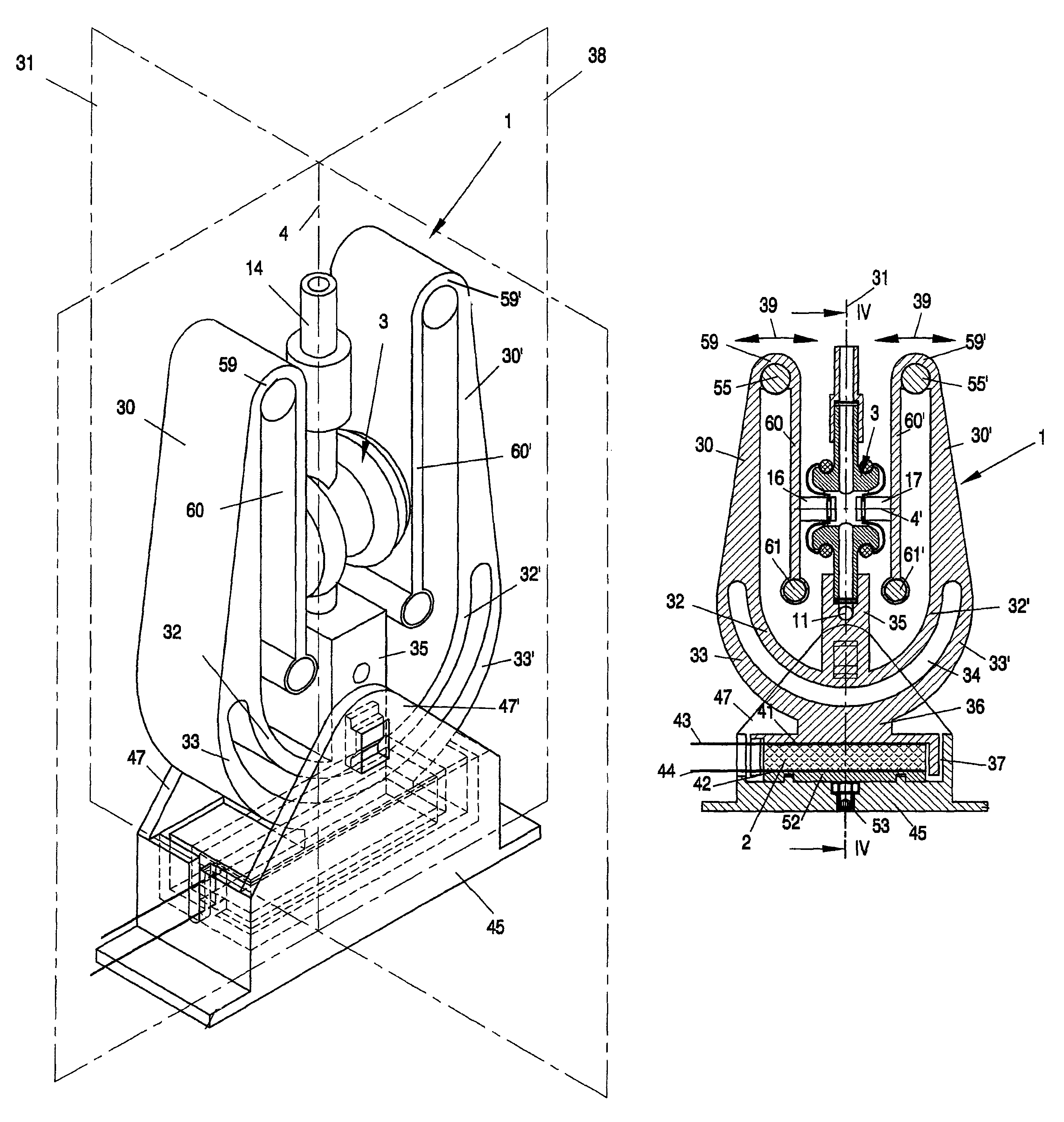
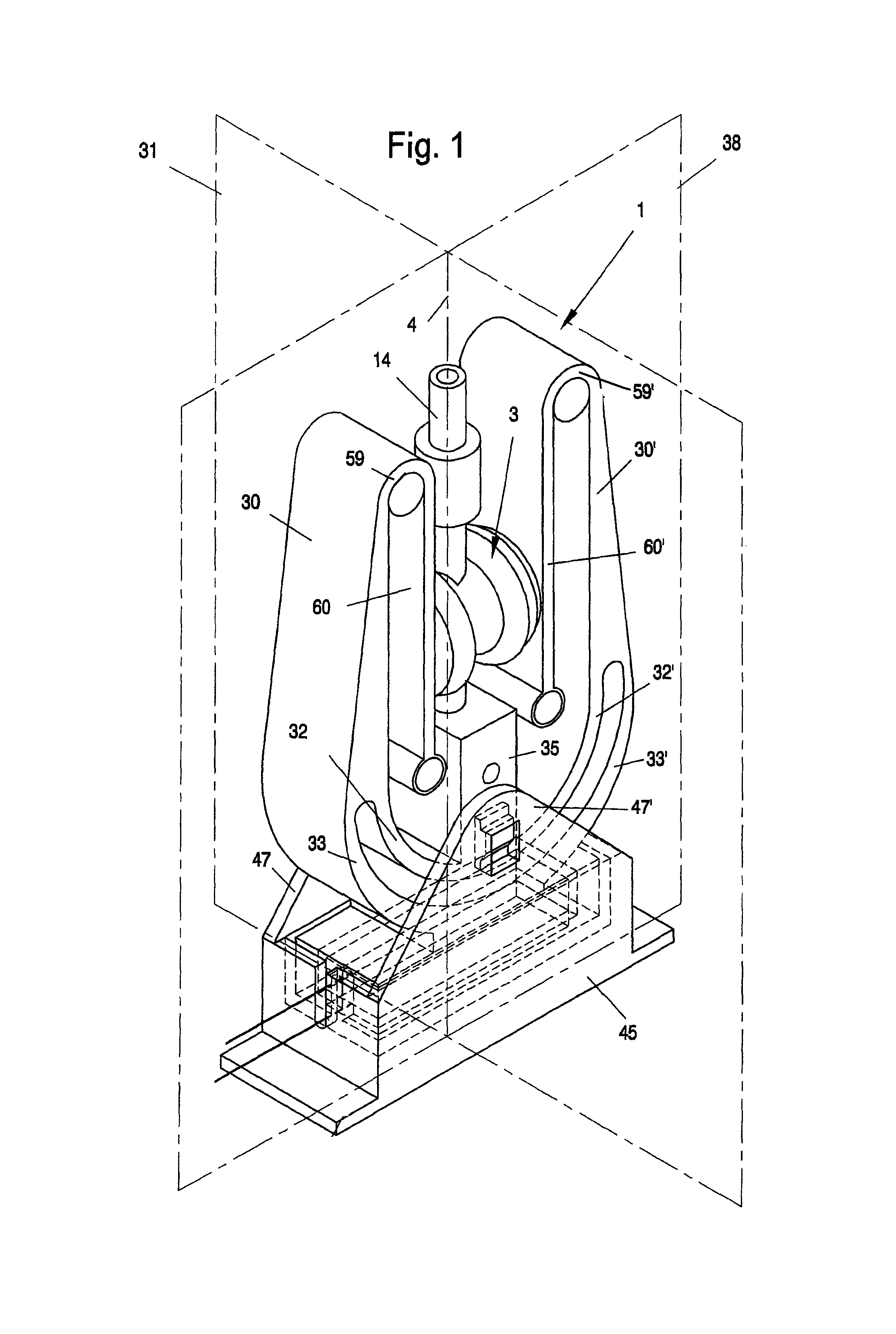
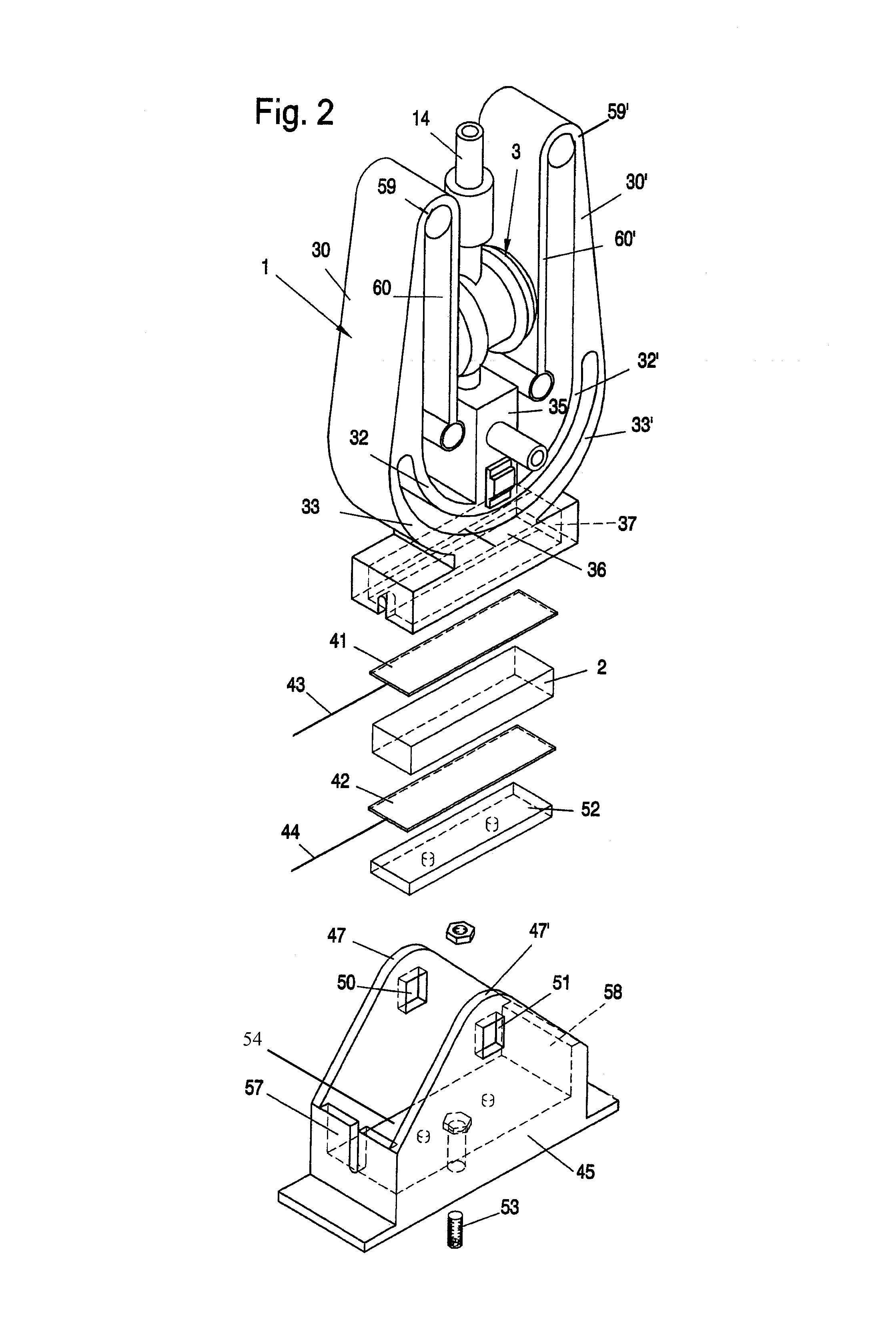
[0049]Referring to the drawings in particular, FIGS. 1 through 4 show a functional exemplary embodiment of an electric oscillating drive, in which an oscillating system 1 of a piezo actuator 2 (FIG. 2) is provided for actuating a fluid pump 3. The fluid pump 3 is a diaphragm pump, which has as the working members or pumping members two pump diaphragms 6 and 7, which are arranged symmetrically to a vertical central axis 4 (FIG. 1) and coaxially to one another with a common horizontal axis 4′ and are associated with a common pump chamber 5 (FIG. 3 and FIG. 3a). These pump diaphragms 6 and 7 are arranged in a self-holding manner on the two opposite sides of a pump body 8. The pump chamber 5, which is in connection with a suction hole 11 via a suction channel 9 and a suction valve 10, is located in this pump body 8. The pump chamber 5 is connected on the delivery side to a connection sleeve 14 via a discharge channel 12 and a discharge valve 13. Any desirable device to be operated with ...


PUM


Abstract

An electric oscillating drive with at least one oscillating system (1), which is driven in an oscillating manner by an actuator, especially a piezo actuator (2) or an oscillating armature magnet generating periodic force pulses with a small motion amplitude with adapted natural frequency in a preset plane (31). At least one oscillating arm (30′) performing oscillating motions has a resonant mass (55′) and with a balance arm (60′), which is in mechanical driving connection with a working member (7) of a working device, especially of a pump (3), which working member is to be driven in an oscillating manner. The oscillating arm (30, 30′) is fastened to two levers of unequal length, namely a control arm (32′) and a driving lever (33′). At least one of these two levers, especially the control arm (32′), is flexurally elastic at least in some sections.

Description

CROSS REFERENCE TO RELATED APPLICATIONS[0001]This application claims the benefit of priority under 35 U.S.C. §119 of German Patent Application DE 20 2008 007 730.3 filed Jun. 10, 2008, the entire contents of which are incorporated herein by reference.FIELD OF THE INVENTION[0002]The present invention pertains to an electric oscillating drive with at least one actuator, especially a piezo actuator or an oscillating armature magnet, which generates periodic force pulses with a small motion amplitude, with an oscillating system driven in an oscillating manner with an adapted natural frequency in a preset plane, which said system has at least one oscillating arm performing pendular oscillating motions with a resonant mass and with a balance arm, which is in mechanical drive connection with a working member of a working device, especially a pump, which said working member is to be driven in an oscillating manner via a coupling member of the balance arm.BACKGROUND OF THE INVENTION[0003]A p...

Claims


Application Information

Patent Timeline
Patent Type & Authority Patents(United States)
IPC IPC(8): H02K7/065F04B19/00F04B17/03H02N2/00B06B1/06F04B37/00H02K33/00
CPCF04B17/003F04B17/04F04B43/04H01L41/0906F04B45/043F04B45/047F04B43/046H10N30/202
Inventor RICHTER, SIEGFRIED
Owner RICHTER SIEGFRIED
Learn More