Traveling system transmission structure for vehicle

a transmission structure and travel system technology, applied in fluid gearings, transportation and packaging, gear units, etc., can solve the problems of deteriorating efficiency in assembling these units into the transmission case, radial expansion of gear units, and difficulty in assembling planetary gear units and forward/rearward travel switch units to the transmission cas

Active Publication Date: 2012-12-25
KANZAKI KOKYUKOKI MFG
View PDF11 Cites 7 Cited by
  • Summary
  • Abstract
  • Description
  • Claims
  • Application Information

AI Technical Summary

Benefits of technology

[0023]In view of the prior art, it is a first object of the present invention to provide a traveling system transmission structure for a vehicle including a planetary gear unit that has a first component and a second component for respectively receiving a constant-speed rotational power and a variable-speed rotational power and also has a third component for outputting a combined rotational power formed by combining the rotational powers of the first and second components, a forward / rearward-travel switch unit that operatively receives the combined rotational power outputted from the third component, and a transmission case that accommodates the planetary gear unit and the forward / rearward-travel switch unit, the traveling system transmission structure being capable of enhancing freedom regarding reduction ration of the planetary gear unit without involving enlargement of the planetary gear unit as well as improving efficiency in assembling the planetary gear unit and the forward / rearward-travel switch unit into the transmission case.
[0024]Further, it is a second object of the present invention to provide a traveling system transmission structure for a vehicle in which an HST, a planetary gear unit is connected one another in series, the HST is shifted in a non-stepwise manner from a first maximum output state of outputting the rotational power that has a maximum rotational speed in one of the normal and reverse directions to a second maximum output state of outputting the rotational power that has a maximum rotational speed in the other one of the normal and reverse directions in accordance with manipulation of a speed-change operating member from an initial position to a maximum operating position, and the planetary gear unit is shifted from a substantially non-output state to a maximum output state as the HST is shifted from the first maximum output state to the second maximum output state, the traveling system transmission structure being capable of reliably realizing a vehicle stop state without necessity of strict accuracy in manufacturing and assembling the HST and the planetary gear unit as well as necessity of strict accuracy of control.
[0031]The traveling system transmission structure for a vehicle according to the first aspect of the present invention makes it possible to enhance freedom regarding reduction ration of the planetary gear unit without involving enlargement of the planetary gear unit, and also improve efficiency in assembling the planetary gear unit and the forward / rearward-travel switch unit into the transmission case.
[0050]The traveling system transmission structure for a vehicle according to the second aspect of the present invention makes it possible to effectively expand a variable range of travel speed in both forward-travel and rearward-travel directions.
[0051]Further, the travel system transmission structure makes it possible to reliably realize the vehicle stop state without necessity of strict accuracy in manufacturing and assembling the HST and the planetary gear unit as well as necessity of strict accuracy of control, since the travel system transmission structure includes the hydraulic brake unit that operatively applies a braking power to the driving wheel in accordance with supply or discharge of hydraulic fluid and is configured so as to cause the hydraulic brake unit to be brought into a brake actuating state upon the power-neutral state of the HST in which the output of the HST is fallen within a predetermined range with the maximum rotational speed in one of the normal and reverse directions with a reference.

Problems solved by technology

However, the conventional traveling system transmission structure described in Patent Document 1 has problems that the planetary gear unit is radially enlarged as well as that the planetary gear unit and the forward / rearward-travel switch unit are difficult to be assembled to the transmission case.
In the configuration described above, the forward / rearward-travel switch unit and the planetary gear unit need to be installed into the transmission case from the front end thereof, thereby resulting in another problem of deteriorated efficiency in assembling these units into the transmission case.
However, on the other hand, there arise problems that the HST and the planetary gear unit need to be accurately manufactured as well as to be controlled with higher accuracy in order to realize a vehicle stop state.
However, repetition of such control cycles possibly causes hunting motion of the vehicle as well as requires highly accurate control.

Method used


Image

  • Traveling system transmission structure for vehicle
  • Traveling system transmission structure for vehicle
  • Traveling system transmission structure for vehicle

Examples


first embodiment

[0088]Described below with reference to the accompanying drawings is a traveling system transmission structure of a vehicle according to a preferred embodiment of the present invention.

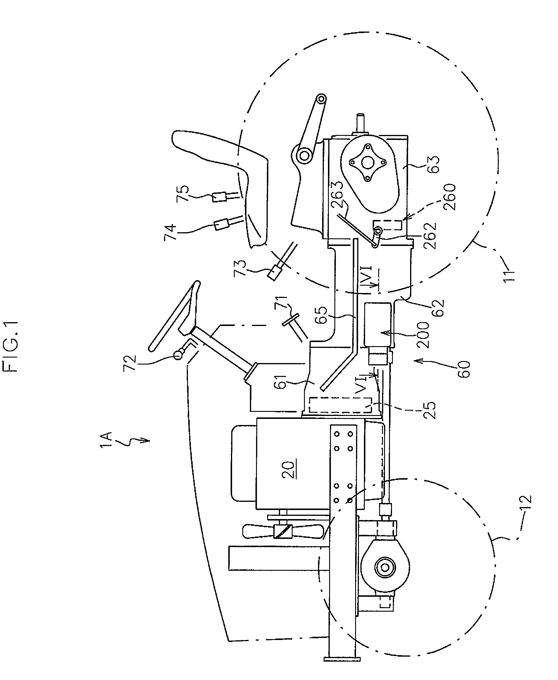
[0089]FIG. 1 is a side view of a tractor exemplified as a working vehicle 1A to which the traveling system transmission structure according to the present embodiment is applicable.

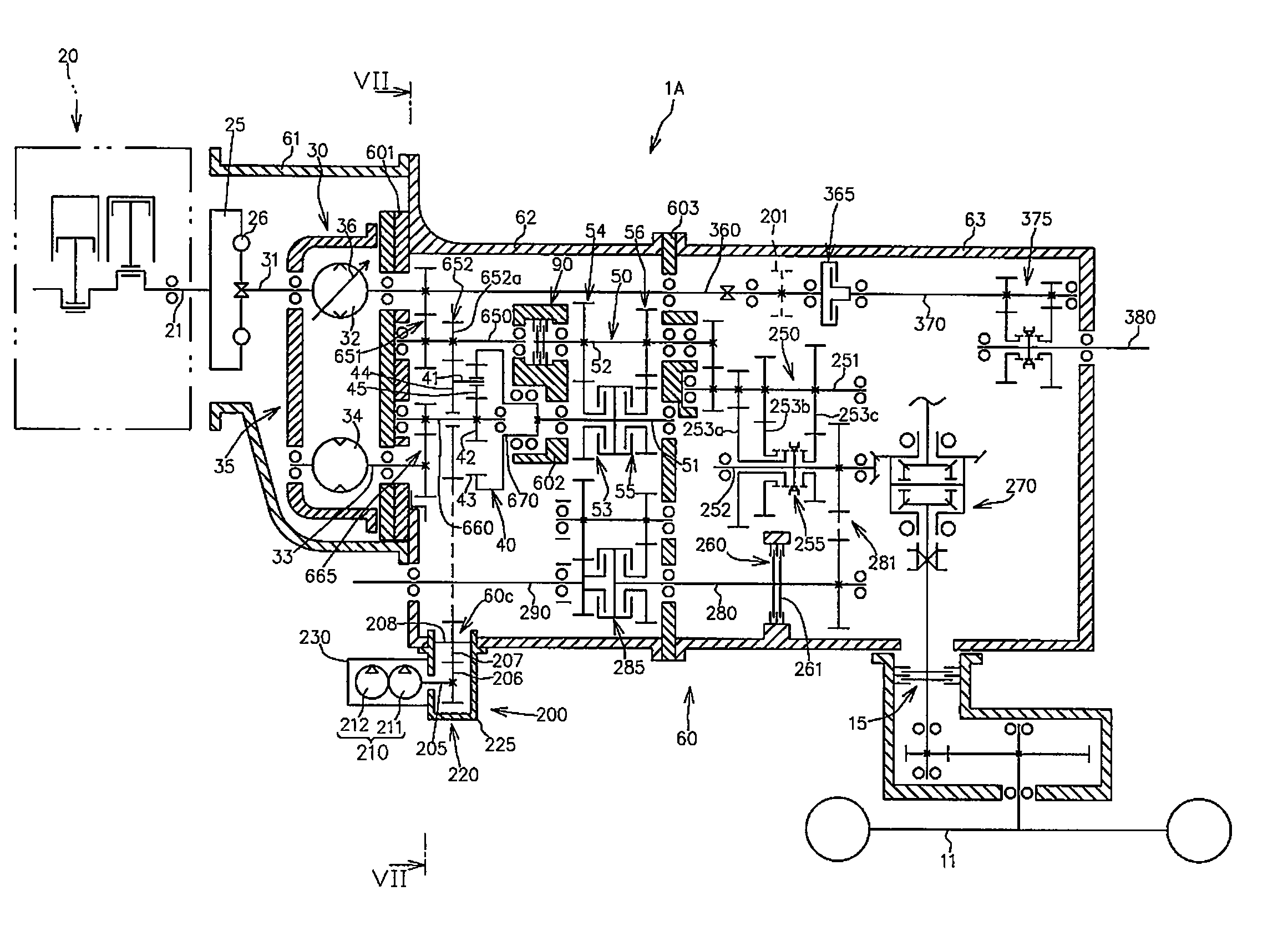
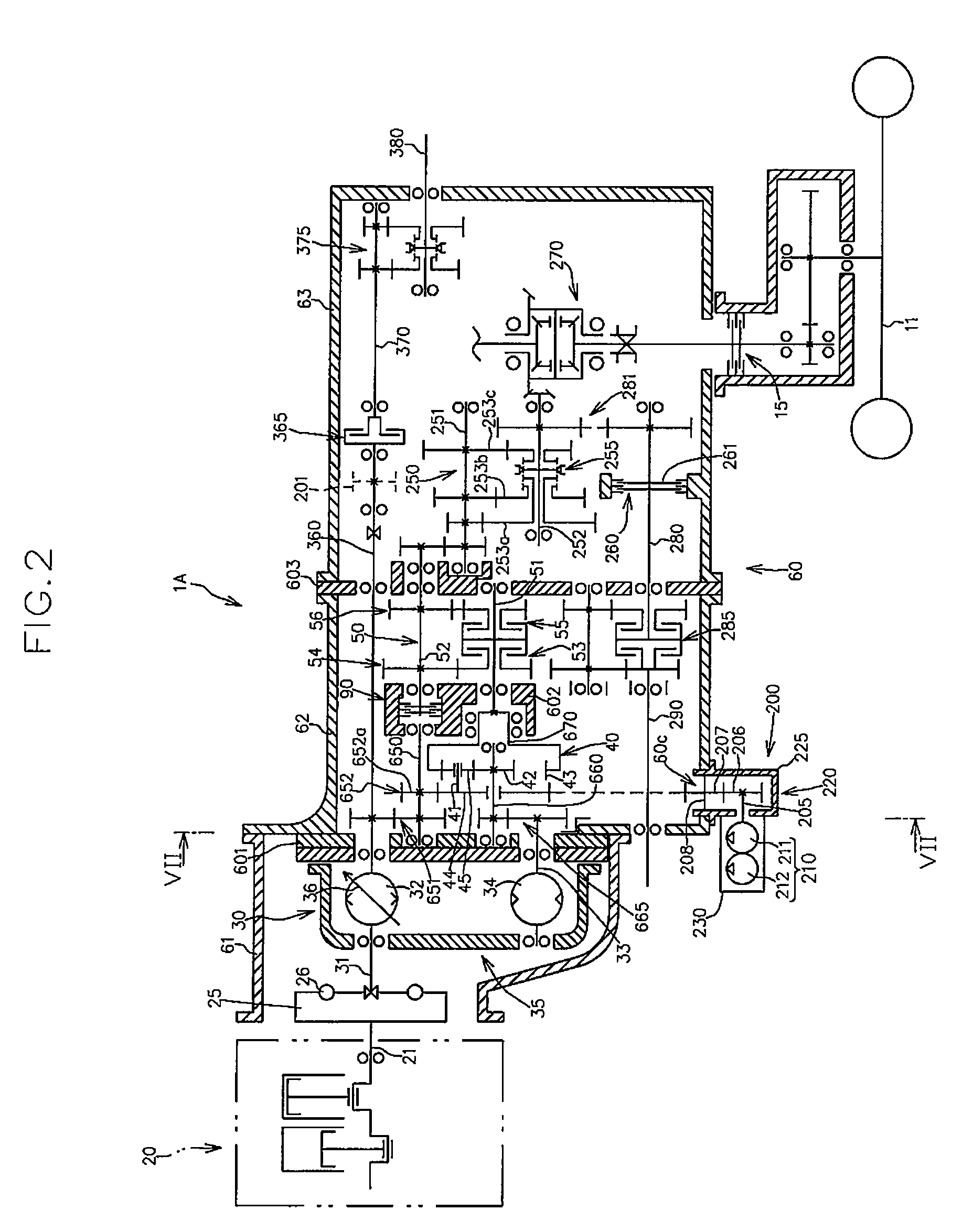
[0090]FIGS. 2 and 3 are a schematic view of a power transmission and a hydraulic circuit diagram of the working vehicle 1A, respectively.

[0091]As shown in FIGS. 1 to 3, the working vehicle 1A includes main driving wheels 11 and sub driving wheels 12 that are disposed on a first side (a rear side in the present embodiment) and on a second side (a front side in the present embodiment) respectively in a vehicle lengthwise direction, a driving power source 20, an HST 30 that is operatively driven by the driving power source 20 and functions as a main speed-change unit, a planetary gear unit 40 that operatively receives a constan...

second embodiment

[0277]Described below with reference to the accompanying drawings is a traveling system transmission structure according to another embodiment of the present invention.

[0278]FIGS. 11 and 12 are a schematic view of a power transmission and a hydraulic circuit diagram of a working vehicle 2A, to which the traveling system transmission structure according to the present embodiment is applied.

[0279]In the drawings, inclusive of FIGS. 11 and 12, which are to be referred in the present embodiment, the members same as those in the first embodiment described above are denoted by the same reference numerals, and detailed description thereof will appropriately not be repeated in the present embodiment.

[0280]Similarly to the traveling system transmission structure of the first embodiment, the traveling system transmission structure according to the present embodiment includes a planetary gear unit 40B that has first and second components for receiving a constant-speed rotational power and a va...


PUM


Abstract

The traveling system transmission structure for vehicle includes a planetary gear unit, a forward / rearward-travel switch unit and a transmission case. A front end portion of a sun gear shaft is directly or indirectly supported by a front bearing wall that is detachably connected to a front side of the transmission case and a rear end portion of a planetary outputting member is directly or indirectly supported by an intermediate bearing wall, so that the planetary gear unit is accommodated in a front chamber that is sandwiched by the front bearing wall and the intermediate bearing wall. A front end portion of a forward / rearward-travel input shaft is directly or indirectly supported by the intermediate bearing wall and a rear end portion of a clutch shaft is supported by a rear bearing wall that is detachably connected to the rear side of the transmission case, so that the forward / rearward-travel switch unit is accommodated in a rear chamber that is sandwiched by the intermediate bearing wall and the rear bearing wall.

Description

BACKGROUND OF THE INVENTION[0001]1. Field of the Invention[0002]The present invention relates to a traveling system transmission structure for a vehicle in which a planetary gear unit and a forward / rearward-travel switch unit are arranged in series.[0003]2. Related Art[0004]There has been publicly known a traveling system transmission structure including a planetary gear unit that has first and second components for receiving a constant-speed rotational power and a variable-speed rotational power respectively as well as a third component for outputting a combined rotational power of the constant-speed power and variable-speed rotational power, a forward / rearward-travel switch unit that operatively receives the combined rotational power outputted from the third component, and a transmission case that accommodates the planetary gear unit and the forward / rearward-travel switch unit (see, for example, Japanese Patent Unexamined Publication No. 2003-130174 (hereinafter, referred to as Pa...

Claims


Application Information

Patent Timeline
Patent Type & Authority Patents(United States)
IPC IPC(8): F16H47/04B60K17/08B60K17/10F16D25/0638F16H1/28F16H3/72F16H47/02F16H57/02F16H57/04
CPCF16H47/04F16H57/021B60K17/28F16H2037/0886F16H2057/02043F16H37/02F16H1/46
Inventor IWAKI, KOJIISHINO, FUMITOSHIKANENOBU, HIDEKIKOGA, KAZUNARIISHII, NORIHIROOKANISHI, TOSHIAKI
Owner KANZAKI KOKYUKOKI MFG
Why Eureka
Try Eureka