Spark ignition type internal combustion engine

a technology of internal combustion engine and spark ignition, which is applied in the direction of machines/engines, electric control, instruments, etc., can solve the problems of reducing the purification rate of unburnt hc by no longer being able to rapidly raise the temperature of the exhaust purification catalyst, so as to suppress the deterioration of the exhaust emission and increase the fuel consumption efficiency

Active Publication Date: 2013-01-01
TOYOTA JIDOSHA KK
View PDF20 Cites 3 Cited by
  • Summary
  • Abstract
  • Description
  • Claims
  • Application Information

AI Technical Summary

Benefits of technology

[0006]Therefore, in view of the above problems, an object of the present invention is to provide a spark ignition type internal combustion engine able to raise the expansion ratio to raise the fuel consumption efficiency at the time of engine low load operation and able to rapidly raise the temperature of the exhaust purification catalyst and able to suppress deterioration of the exhaust emission at the time of cold start.
[0010]Therefore, according to the above aspect, before the internal combustion engine finishes warming up, the drop in the temperature of the exhaust gas is suppressed. Therefore, at the time of engine cold start, it is possible to rapidly raise the temperature of the exhaust purification catalyst, while after the internal combustion engine finishes warming up, it is possible to increase the expansion ratio and raise the fuel consumption efficiency at the time of engine low load operation.
[0014]In a 5th aspect of the present invention, before the internal combustion engine finishes warming up, the mechanical compression ratio is made lower when the temperature of the exhaust purification catalyst provided in the engine exhaust passage is low compared with when it is high.
[0018]In a 9th aspect of the present invention, before the internal combustion engine finishes warming up, the actual compression ratio is made lower when the temperature of the exhaust purification catalyst is low compared with when it is high.
[0019]In a 10th aspect of the present invention, before the internal combustion engine finishes warming up, the actual compression ratio is made lower when the temperature of the exhaust purification catalyst is low compared with when it is high.
[0020]In a 11th aspect of the present invention, before the internal combustion engine finishes warming, the actual compression ratio is made lower when the temperature of the engine cooling water is low compared with when it is high.

Problems solved by technology

Therefore, if raising the expansion ratio at the time of cold startup, it is no longer possible to rapidly raise the temperature of the exhaust purification catalyst.
Further, at the time of engine cold start, the purification rate of unburnt HC by the exhaust purification catalyst falls.

Method used


Image

  • Spark ignition type internal combustion engine
  • Spark ignition type internal combustion engine
  • Spark ignition type internal combustion engine

Examples


first embodiment

[0094]Therefore, in the present invention, at the time of engine cold start, the superhigh expansion ratio cycle is not executed even at the time of the above-mentioned engine low load operation.

[0095]FIG. 10 is a view showing changes in the mechanical compression ratio, expansion ratio, closing timing of the intake valve 7, intake air amount, and opening degree of the throttle valve 17 in accordance with the engine load at the time of engine cold start. FIG. 10 shows only the region where the load is relatively low. Note that, the broken line in the figure shows the changes in the parameters when executing superhigh expansion ratio control executing a superhigh expansion ratio cycle at the time of engine low load operation. Further, in FIG. 10, the case of controlling the intake air amount by delaying the closing timing of the intake valve 7 as the engine load becomes lower is explained, but similar control is possible even when controlling the intake air amount by advancing the cl...

second embodiment

[0128]FIG. 14 is a flowchart showing the control routine of operational control of the internal combustion engine in a The illustrated control routine is performed by interruption every constant time interval.

[0129]As shown in FIG. 14, first, at step S20, in the same way as step S11 shown in FIG. 11, the operating state of the internal combustion engine is detected. Next, at step S21, it is judged if the internal combustion engine, in particular, the three-way catalyst 21, has finished warming up. At the time of engine cold start, it is judged that the internal combustion engine has not finished warming up, then the routine proceeds to step S22. At step S22, it is judged that the internal combustion engine has already been started. Before the internal combustion engine is started, the routine proceeds to step S23 where the temperature of the three-way catalyst 21 is detected. The temperature of the three-way catalyst 21 is detected right before engine start, so the temperature of t...

third embodiment

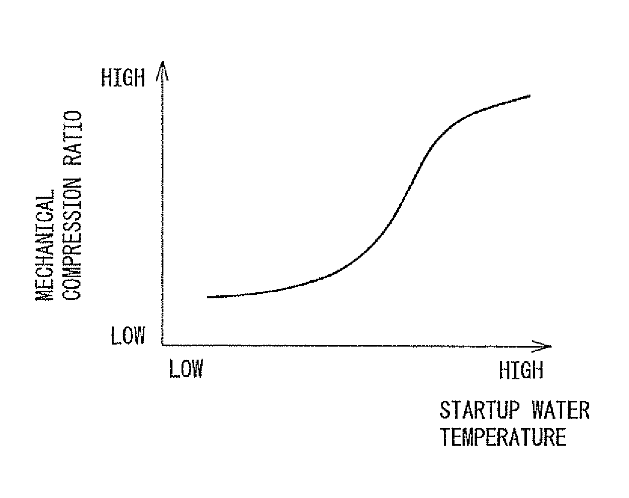
[0140]FIG. 16A and FIG. 16B are views showing the relationships between the temperature of the engine cooling water at the time of engine start and the mechanical compression ratio and between the temperature of the engine cooling water at the time of engine start and actual compression ratio. As shown in FIG. 16A, in the present embodiment, in the same way as the third embodiment, the lower the temperature of the engine cooling water at the time of engine start, the lower the mechanical compression ratio at the time of engine start is set. That is, the mechanical compression ratio at the time of engine start is made lower when the temperature of the engine cooling water at the time of engine start is low compared with when it is high.

[0141]Further, as shown by the solid line in FIG. 16B, in the present embodiment, in the temperature region where the temperature of the engine cooling water is higher than a reference temperature (hereinafter referred to as the “high temperature side ...


PUM


Abstract

Disclosed is a spark ignition type internal combustion engine, which comprises a variable compression ratio mechanism capable of changing a mechanical compression ratio, and a variable valve timing mechanism capable of controlling the closing timing of an intake valve. The intake air flow to be fed to the inside of a combustion chamber is controlled mainly by changing the closing timing of an intake valve so that the mechanical compression ratio is set higher at an engine low-load running time than that at an engine high-load running time. The mechanical compression ratio at the engine low-load running time before completion of the warm-up of the internal combustion engine is set lower than that at the engine low-load running time after completion of the warm-up of the internal combustion engine. Although the expansion ratio at the engine low-load running time is raised to improve the mileage, it is possible at an engine cold start to heat an exhaust purifying catalyst promptly and to suppress the deterioration of an exhaust emission.

Description

TECHNICAL FIELD[0001]The present invention relates to a spark ignition type internal combustion engine.BACKGROUND ART[0002]Known in the art is a spark ignition type internal combustion engine provided with a variable compression ratio mechanism able to change a mechanical compression ratio and a variable valve timing mechanism able to control a closing timing of an intake valve, performing a supercharging action by a supercharger at the time of engine medium load operation and at the time of engine high load operation, and increasing the mechanical compression ratio and delaying the closing timing of the intake valve as the engine load becomes lower in a state holding an actual compression ratio constant at the times of these engine medium and high load operations (for example, see Japanese Patent Publication (A) No. 2004-218522).[0003]In this regard, a spark ignition type internal combustion engine improving a heat efficiency at the time of vehicle operation to obtain a better fuel...

Claims


Application Information

Patent Timeline
Patent Type & Authority Patents(United States)
IPC IPC(8): F02B75/04F01L1/34
CPCF02D13/0261F02D15/02Y02T10/18F02D41/0025F02D2200/0611Y02T10/12
Inventor YOSHIOKA, MAMORUAKIHISA, DAISUKEKAMIYAMA, EIICHINAKASAKA, YUKIHIRO
Owner TOYOTA JIDOSHA KK
Why Eureka
Try Eureka